Download
1 / 28
290 likes | 445 Vues
Space structures. Space mission environments: sources for loading and structural requirements. Prof. P. Gaudenzi Università di Roma La Sapienza, Rome Italy paolo.gaudenzi@uniroma1.it. THE STRUCTURAL SYSTEM OF A SPACECRAFT. The structural system of a spacecraft has three main functions:

E N D
Space structures Space mission environments: sources for loading and structural requirements Prof. P. Gaudenzi Università di Roma La Sapienza, Rome Italy paolo.gaudenzi@uniroma1.it
THE STRUCTURAL SYSTEM OF A SPACECRAFT • The structural system of a spacecraft has three main functions: • To provide the support of all the other subsystem and materialize the geometry of the spacecraft and its payloads; • To guarantee the necessary STRENGTH to survive all phases of the spacecraft life (in particular the most critical: e.g. the launch) without failures. • To keep the structural STIFFNESS in certain limits to guarantee the operational functionality of the overall system and avoid coupled resonant responses (e.g. between a satellite and its launcher). • Since the cost of mass is very critical in a space mission, the structural system should be optimized with respect to it both in terms of material and in terms of the optimal structural geometries.
NATURAL AND INDUCED ENVIRONMENT (ECSS 4.2.2) • All structural assemblies and components shall be able to withstand the environment loads and conditions to which they are exposed both during manufacture and their complete service-life. • b. Components and assemblies for space applications shall be compatible with the operational environment conditions and with the atmospheric conditions on earth in which they are manufactured and tested. • c. Consideration shall be given to effects of gravitation and exposure of sensitive materials to manufacturing and atmospheric environments; suitable provisions (e.g. gravitational compensation and purging) shall be made where necessary for the protection of sensitive equipment or components.
NATURAL AND INDUCED ENVIRONMENT (2) The sensitivity of materials to the environment on earth can stipulate the requirements for quality control procedures. The natural environment generally covers the climatic, thermal, chemical and vacuum conditions, required cleanliness, levels of radiation and the meteoroid and space debris environment. The induced environments cover the mechanical loads induced by ground handling and pre-launch operations, launch,manoeuvres and disturbances, re-entry, descent and landing. Additional induced environments include static pressure within the payload volume, temperature and thermal flux variations and the electromagnetic and humidity environments.
MECHANICAL ENVIRONMENT (ECSS 4.2.3) a. The mechanical environment shall be defined by static and dynamic environment loads which shall be further defined in terms of constant acceleration, transient, sinusoidal and random vibration, acoustic noise and shock loads. b. All loads shall be considered in the worst combinations in which they occur. The severest loads can be experienced during launch, ascent and separation,and, where relevant during re-entry, descent and landing. However, consideration shall also be given to the other loads which can effect the performance in an operational mode.
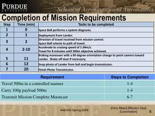
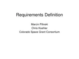
LOADS (ECSS 4.2.10) a. All relevant mechanical and thermal load events experienced throughout the service-life of the structure shall be identified. b. Loads shall be defined according to their nature, static or dynamic, their level and time corresponding to the events during the lifetime, and as a minimum the following load events shall be considered:
LOAD EVENTS (1) 1. Ground and test loads: — handling, transportation and storage loads; — assembly and integration loads; — ground test loads. 2. Launch loads: — launch preparation; — operational pressures; — engine ignition; — thrust build up; — lift-off; — thrust (constant or varying slowly);
LOAD EVENTS (2) 2. Launch loads (continued): — aerodynamic loads; — heat flux from engine and aerodynamics; — gust; — dynamic interaction between the structure and propulsion system; — acoustic noise; — manoeuvres; — thrust decay; — pyrotechnics; — separation of parts (e.g. stage, fairing, spacecraft); — depressurization.
LOAD EVENTS (3) 3. In-orbit loads: — operational pressures; — static and dynamic loads induced by thrusters; — shocks due to pyrotechnical operation and deployment of appendages; — thermo-elastic loads induced by temperature variations,-- hygroscopic-induced load due to variations in moisture content; — micro-vibrations induced by moving elements (e.g. momentum wheels) and thrusters;
LOAD EVENTS (4) 3. In-orbit loads (continued): — micrometeoroids and debris; — docking; — berthing; — crew induced loads (e.g. on handles, rails and by movements). 4. Re-entry, descent and landing: — aerodynamic loads and thermal fluxes; — parachute ejection and deployment shocks; — operational pressures; — landing loads; — impact loads.
GROUND LOADS Example of ground loads sources and corresponding indicative figures
LAUNCH LOADS: AXIAL ACCELERATION ARIANE 5 AXIAL ACCELERATION PROFILE From Arian 5 User’s Manual
DESIGN LOADS FACTORS (from Ariane 5 User’s manual) The design load factors are represented by the Quasi-Static Loads (QSL) that are the more severe combinations of dynamic and steady-state accelerations that can be encountered at any instant of the mission (ground and flight operations). The QSL reflect the line loads at the interface between the spacecraft and the adapter (or dispenser). Also frequency requirements and static moment limitation are imposed. Gravity is included, SRB: solid rocket booster, The Quasi-Static-Loads (QSL) apply on payload C of G, The minus sign with longitudinal axis values indicates compression. From Arian 5 User’s Manual
DESIGN LOADS FACTORS (other launchers) In the following table two other launchers load factors are reported and a possible envelope condition is obtained in the case of a possible launch alternative
STATIC UNBALANCE AND ALIGNMENT REQUIREMENTS • Static unbalance • Spun-up spacecraft The centre of gravity of the spacecraft must stay within a distance d ≤ 30 mm from the launcher longitudinal axis. • b) Three-axis stabilized spacecraft The acceptable static unbalance limit varies with the spacecraft mass as reported BELOW:
FREQUENCY REQUIREMENTS (1) In the table the frequency requirements of different launchers are illustrated. Frequency should be equal or higher than the reported values. Amplification of the dynamic response of a single degree of freedom damped system
FREQUENCY REQUIREMENTS (2) (ARIANE 5) To prevent dynamic coupling between the low-frequency launch vehicle and spacecraft modes, the spacecraft should be designed with a structural stiffness which ensures that the following requirements are fulfilled. Lateral frequencies - The fundamental frequency in the lateral axis of a spacecraft hard-mounted at the interface must be as follows with an off-the-shelf adapter: Longitudinal frequencies - The fundamental frequency in the longitudinal axis of a spacecraft hard-mounted at the interface must be as follows: ≥ 31 Hz for S/C mass < 4500 kg ≥ 27 Hz for S/C mass ≥ 4500 kg
FAIRING ENVELOPE Not a load but a volume and geometry constraint
LOADS FOR PAYLOAD COMPONENTS Dynamic amplification factors or other causes may affect the real loads on components
SINE VIBRATIONS Sinusoidal excitations affect the L/V during its powered flight, mainly the atmospheric flight, as well as during some of the transient phases. The envelope of the sinusoidal (or sine-equivalent) vibration levels at the spacecraft base does not exceed the values given in table aside, taken from Ariane 5 user’s manual.
DEPRESSURIZATION AND VENTING Variation of pressure inside the fairing of Ariane 5
ACOUSTICS Acoustic pressure fluctuations under the fairing are generated by engine operation (plume impingement on the pad during liftoff) and by unsteady aerodynamic phenomena during atmospheric flight (i.e., shock waves and turbulence inside the boundary layer), which are transmitted through the upper composite structures. Apart from liftoff and transonic phase, acoustic levels are substantially lower than the values indicated hereafter. Note: OASPL – Overall Acoustic Sound Pressure Level (reference: 0 dB = 2 x 10⁻⁵ Pa)
SHOCKS The spacecraft is subjected to shocks during L/V stages separation events, mainly fairing jettisoning, and during spacecraft separation. With respect to the L/V shock events, the envelope of the shocks generated during the flight has to be considered. Ariane 5
ON ORBIT ENVIRONMENT: THERMAL FLUX During its on orbit life and according to the characteristics of the orbit, an earth orbiting spacecraft is subjected to sun radiation, albedo and earth radiation. The same is true for other space vehicles orbiting or flying by other planets. The thermal control subsystem is responsible for keeping the spacecraft in the admissible range of temperatures. The variations of temperature generate thermoelastic actions on the spacecraft structures.
CONCLUDING REMARKS Requirements coming from the natural and induced environment Main environment forces and conditions depending upon the phase of the mission (ground, launch, in orbit, descent re-entry) Launching environment and constraints