Download
1 / 50
500 likes | 508 Vues
Research on GDI Internal Combustion Engines @ IITDelhi. P M V Subbarao Professor Mechanical Engineering Department I I T Delhi. Models to Predict New & Better Anatomy of Artificial Horse …. Tracking of Post Injection Events inside Cylinder. New Knowledge Required to Develop GDI Engines.

E N D
Research on GDI Internal Combustion Engines @ IITDelhi P M V Subbarao Professor Mechanical Engineering Department I I T Delhi Models to Predict New & Better Anatomy of Artificial Horse …..
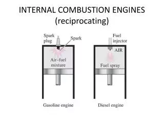
New Knowledge Required to Develop GDI Engines • Effect of Geometrical and Spray Parameters • Injector location, • Spray orientation, • Injection timing, • Droplet diameter, • Spray cone angle, • Type of spray, • Fuel temperature
Required Features of CFD Package • Capability to model flow in complex geometry • Capability to model turbulent flow • Capability of handling moving boundaries • Generalized multi-block capability • Spray model • Robust Algorithm
Initialize all variables Droplet Tracking Algorithm Source terms of Gas Phase Equation = 0 Solve for Gas Phase Equations Solve for Droplet Equations Cal. Gas Phase Source Terms Converged ? No ya Next Time Step
Other Results Obtained from the Code • Effect of Compression ratio on turbulence • Effect of speed on turbulence • Effect of speed on squish generation
Study of Charge Homogenization • Index for deviation from homogeneity
Conclusions for DISC Chamber • The Spray Cone Angle should be as wide as possible • Spray impingement is not avoidable even for smallest droplets • Bigger droplets travel fast to impinge fast – better for further homogenization • The earlier the better • The bigger the better • The wider the better for homogenization
Pent Roof Geometry with Central Injector • Similar studies : 25 – 100 micron, 600 to 1200 • SOI – 900 aTDC (Suction)
Conclusion Pent Roof > DISC for homogenization
Charge Homogenization in Pent Roof Chamber with Side Injector • SOI = 900 • Orientation – 300 from horizontal • Droplet Dia – 100 to 25 micron • Spray Angle – 900 to 1200
Optimum injection conditions for Pent Roof chamber with Side Injector
Study of Charge Stratification in Different Configurations • DISC ChamberPent Roof with Central InjectorPent Roof with Side Injector • SOI – varied • Tumble Ratio - varied
Stratified Charge Formation in Central Injector with Tumbling Flow
Parametric Studies • Tumble Ratio (Maximum gas velocity/piston speed) – 5 to 7.5 • SOI – 900 to 1200 bTDC (Compression) • Dia - 100 micron to 25 micron
Stratified Charge Formation in Side Injector with Tumbling Flow
Parametric Studies • Drop Dia. – 100 micron • Compact Spray – 450 • Orientation of Injector from horizontal – 300, 450,600 • SOI – 900, 1200
Optimum Injection Parameters for Pent roof Geometry with Side Located Injector
Experimental Development • A special purpose test rig was developed in IC engine laboratory of Mechanical Engineering Department, IIT Delhi, to investigate the characteristics of GDI engines. • A four stroke engine of Kawasaki Bajaj two wheeler is modified to work as GDI engine. • A mechanical driven petrol injector is placed in the cylinder head. • Pistons with various geometries of cavities (Cylindrical, Conical & Spherical) are tested using a compression ratio of 9.3 at various speeds. • Following preliminary results are obtained.
Engine Geometric Ratios Engine Compression Ratio Cylinder Bore-to-Stroke Ratio Kinematic Rod Ratio
Controlled Compression Ratio Instantaneous Piston Displacement:
Conclusions • GDI Engine Technology is an obvious future choice. • Extensive CAD is essential for the development of GDI Engines. • CAD combined with experimental study will develop a better engine with faster development cycle. • More avenues for future research and development.