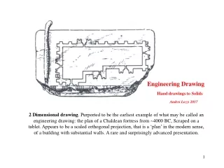
Download
1 / 24
240 likes | 388 Vues
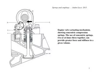
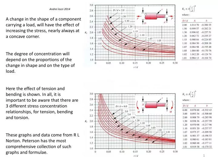
Andrei lozzi 2014. A change in the shape of a component carrying a load, will have the effect of increasing the stress, nearly always at a concave corner. The degree of concentration will depend on the proportions of the change in shape and on the type of load.

E N D
Andrei lozzi 2014 A change in the shape of a component carrying a load, will have the effect of increasing the stress, nearly always at a concave corner. The degree of concentration will depend on the proportions of the change in shape and on the type of load. Here the effect of tension and bending is shown. In all, it is important to be aware that there are 3 different stress concentration relationships, for tension, bending and torsion. These graphs and data come from R L Norton. Peterson has the most comprehensive collection of such graphs and formulae.
This end can be fixed Convex edge, external corner Concave edge, internal corner Tensile load We can verify that FEA will provide very similar (ie relatively precise) values for stress concentrations as those provided by classic sources. The above strap is subjected to tension. The tensile stress in the strap should be inversely proportional to the cross sectional area of the strap. Since the narrow middle of the strap is ½ the height of the ends, the stress at the middle could be expected to be no more than about 2 times that at the fat ends, provided the changes in shape play no part !
For the same ratio of cross-sections, the radius of the concave corner has significant effect on the stress level at the beginning of the radius of the fillet. Stress concentration of ~ 1.5 Stress concentration of ~ 3
The concave corner with the larger radius above, has a stress level of about 1.5 of that of the thin middle of the strap. The fat end has about half the stress of the thin middle, as expected. The convex corner has about 1/200 the stress of the middle ! Had we analysed a strap with perfectly sharp convex corners, with increasingly smaller FEA elements, we would have found a stress level at the corners, that would tend to increase to infinity, as the elements get smaller ! Hence convex corners should be filleted to as large a radius as practical and convex corner, although may be left sharp should preferably be chamfered Convex corner A sizeable fillet has been added to the concave corner
Quarter ellipses seem to be some sort of ideal fillets, generating stress concentration of just over 1. Some may say that deal components should be uniformly stressed, which would result in smoothly and continuously sculptured parts. Such parts would typically be so costly that they would turn up in military planes and F1 cars, and our FSAE car of course. The outline of a quarter of a long ellipse The under-stressed convex corner could be chamfered or a second quarter ellipse could be blended into the first.
We can retain a shoulder if it is required in the machine assembly while reducing stress concentration by adopting geometries that reduce the stiffness of the shoulder. Note that here a hole is used, which obviously appears to be a little too large and not in good locations. Note also that here and some of the previous slides, advantage has been made of the planes of symmetry in the straps, to reduce the number of elements by factor of 4, and to remove the error inducing effect of having a fixed and unchanging end face.
Welded and Bolted bases. Good and poor examples of web and hold-down bolt placements For you to consider ….
a) b) c) MR P Orlov, Mir publishing, Moscow, has the above figure in one of his books. We have a triangulated frame above and a cantilever beam below it. In a) the cantilever beam is of the same section as those making up the frame, its highest tress is about 10 000 times the stresses in the frame. In b) the diameter of the cantilever beam is increased so that its maximum stress is the same as that in the frame. Finally in c) the diameter is increased so that the deflection is the same as that in the frame. Please note what happened to the mass increase of the cantilever beam, X 64 X 120. But But mass may not be the whole consideration, because you may not have the room for a frame.
A L Brackets Thick & Thin There are in-out forces at the hole A on the 100 mm leg. This generates a bending moment on this leg. It can be resisted by a couple (two forces) at holes on the 60 mm leg Unfortunately bending moments tend to create the largest stresses and deflection in parts that we make using the sort of materials and sections we find useful. Consequently we try to get rid of the bending moment in the 100 mm leg by ‘triangulating’, ie adding a web that goes from the load to the reaction in straight line.
The web welded to one side of the narrow bracket deals with the biggest bending moment, about the X axis but not the lesser moment about the Y axis. Of course the deflection about Y may be tolerable to you, but it will require a relatively heavier bracket, now for satellites and FSAE cars that is not good enough ! X Y
Now if the boss is not going to sack you, could consider a web that removes both moments about X and Y axes at the same time. I have added bosses (very thick washers welded in place) at the bolt locations, because no matter what you do the highest stresses will be almost certainly around the bolt holes. These bosses are optional if you can tolerate distortion around the bolt holes Note this web is aligned with all the forces and reactions and has cut-outs intended to provide access with nuts, washers and tools. This solution may seem a little over the top but in many situations it is the design of choice.
But the forces of evil will not rest … The not so smart graduate from the other university, will insist that two webs will be better than one and with sufficient holes access is not denied to real toolies.