Download
1 / 14
140 likes | 286 Vues
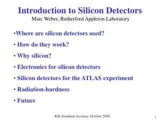
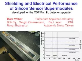
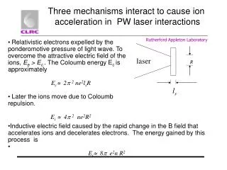
Critical areas and ATLAS next steps Marc Weber (Rutherford Laboratory). A few obvious comments on: RO chip power Critical issues for DC-DC Critical issues for Serial Powering ATLAS power plug-in boards. RO Chip Power.

E N D
Critical areas and ATLAS next steps Marc Weber (Rutherford Laboratory) • A few obvious comments on: • RO chip power • Critical issues for DC-DC • Critical issues for Serial Powering • ATLAS power plug-in boards
RO Chip Power Low power matters for module thermal management. Low current matters for cable losses. Reducing current is more effective than optimizing cable resistance/rad. length (I2R). Reduced currents will greatly simplify power distribution and power electronics. ATLAS strips ROIC history and future (current per 128-channel chip) • Analog voltage will be higher than digital voltage! For 0.25 μm ABC-Next analog voltage is derived from digital. ~300 mV difference between Vcc and Vdd is natural. What for 0.13 μm ABC-Next? Expect digital voltage to be derived from analog. (Rather than separate power lines or DC-DC step-up or step-down conversion.) A voltage difference of more than ~300 mV difference between Vcc and Vdd does not help. Value depends on need for SEU protection
RO Chip Power (continued) • Digital power will be significantly higher than analog powerfor short strips focus on digital current reduction now • Constant current consumption vs. lower (average) current My prejudice is that constant current will be very beneficial for optimum hybrid performance simply switching clocks off where possible might not be enough What could be done ? I have no obvious answer, but feel that much more than incremental power savings are possible (at cell level; chip level; system level) Analyze where digital power is spent and identify improvements; optimize RO architecture for power; put common logic into module controller chip; Increase number of channels per chip, etc.
DC-DC critical issues Disclaimer: I will only mention two, which I feel are most urgent to date • DC-DC converter induced “pick-up” Excess noise through coupling between air-coil and strips has been observed by several groups (Yale, RAL, BNL, Aachen). The size of the effect depends on shielding, distance to sensor, etc. Our target should be “zero” excess noise. I believe this is achievable. We will get more results when the first upgrade prototype modules become available. For ATLAS this might happen by the end of this year. • DC-DC converter gain So far we have been limited to gain 4. We need to be more ambitious. Either by gain ~10 devices (preferred) or two stage converter systems. The example below shows why
Efficiency examples Disclaimer: My numbers are just reasonable guesses and contain several simplifications. Put in your own numbers! Assumptions: hybrid current/voltage/power: 2 A/1.2 V/ 2.4 W; cable resistance: 2 Ohms these numbers are optimistic 20 hybrids per stave side; 48 W per stave side; regulator/converter inefficiency: 15% (for SP the inefficiency considers current variations with time and between modules) Four scenarios • SP with 20 hybrids in series; inefficiency 15% ~ 11 W cable losses • DC-DC with gain 10; inefficiency 15% ~ 44 W losses • DC-DC with gain 4 * 2; inefficiencies 15% and 10% ~ 85 W losses • DC-DC with gain 4; inefficiency 15% ~ 277 W losses This suggests: Let’s work hard for high gain! We can do better than a gain of four. DC-DC with gain 10 keeps power efficiency at LHC levels. This is would be a great achievement. Serial powering with 20 or more hybrids in series is even better
Serial powering critical issues • Custom SP circuitry We are almost there. Design of custom circuitry for strips and of the general purpose SPi chip for strips or pixels was a major enterprise. Getting functional chips back will clearly make a huge difference for this R&D. Need to explore all three architectures and understand which is most suitable for the final system. Only one can be taken. Which one is entirely open as of today. All-internal scheme All-external scheme/SPi scheme Mixed scheme Parallel shunt regulators & shunt transistors ATLAS pixels (Bonn) and strips (W. Dabrowski) One external shunt regulator and transistor M. Trimpl (FNAL), RAL, UPenn One external shunt regulator – many parallel shunt transistors M. Newcomer (UPenn)
Serial powering protection schemes The risk of losing all modules in series through a fault is an obvious concern with serial powering. While the reduced number of connections provides some protection, more can be done. (Protection is also important for DC-DC in particular with parallel powering, less with independent powering) • There are two distinct tasks 1) Slow-control: switch module to stand-by (lowest achievable voltage across it); bridge broken current path. 2) Real-time protection: over-voltage; excessive power through shunt transistor The best schemes is yet to be found, but for the next round of supermodule construction, we should implement the best we can. This will be discrete components.
Conceptual schemes in the making • Bonn scheme Power FET driven by slow-control shorts module to reduce thermal load or for a fault. Simple; low-voltage drop; the extra control lines can be used for voltage sensing • BNL scheme Overvoltage protection, latch and alternative current path. Real-time protection and stand-by enabled through slow-control; one-wire system • SPi protection features Low-voltage mode and current sensing ADC plus current alarm. No real-time activation of protection in this iteration
Serial powering protection (continued) A little more thinking and simulation is needed to identify the optimum scheme. Questions to address: • Where to place the protection circuitry (on or off-hybrid) ? • Individual control lines or one-wire system ? • Optimum schematic (e.g. how to achieve low voltage drop) • How to combine protection elements in one chip or how minimize the number of technologies Choices may well be system dependent and be different for strips and pixels. Need to gain practical experience with these schemes.
ATLAS next steps Hope to build a prototype silicon stave (electrical testbed or more) within the next 6 months or so. Features: • ABC-Next 0.25 μm CMOS • 20-chip hybrids • p-on-p short strips sensors (sensor area 10 cm x 10 cm) • 10 or 12 single sided modules on either side This supermodule is the best power test-bed we will get in a while. Let’s make good use of it !! First step is a power plug-in board to talk to hybrid and modules. (Next steps are not entirely clear today, but I advocate a more integrated power unit)
Sketch of SP plug-in board VDD GNDD VCC GNDA VDD GNDD VCC GNDA ShuntCtl1L ShuntCtl2L ShuntCtl1R ShuntCtl2R REGDIS (ShuntLim1) (ShuntLim2) ShuntDisable Clk ClkB Com ComB Data0 Data0B Data1 Data1B ClkMode80 Reset ResetB L1 L1B BC BCB Power PCB SPi / Op-amp Hybrid Protect Protection DCS Monitoring Voltage/current To stave bus cable To hybrid Still missing: agreed interfaces to hybrid and bus cable; definition of slow-control block; full schematic; size estimate
Plug-in boards (continued) Each power scheme is expected to provide a plug-in board. This is a wonderful testing opportunity for each approach and allows physicists to get used to it. Module performance can be compared for either approach. For now the following information is needed: Output and input lines Size estimate Very brief description of specs (mostly gain, max. current, efficiency) Given this, the common interfaces for all boards can be defined and we can request real-estate and a minimum number of bus lines, etc. for power ...
Let’s discuss all these issues in the next few days ... and monthsThank you!