Download
1 / 16
160 likes | 398 Vues
Channel Impairments. Outline. Analog communication systems Channel impairments Hybrid communication systems Analog pulse amplitude modulation. Communication System Structure. Information sources Voice, music, images, video, and data (baseband signals) Transmitter

E N D
Outline • Analog communication systems • Channel impairments • Hybrid communication systems • Analog pulse amplitude modulation
Communication System Structure Information sources Voice, music, images, video, and data (baseband signals) Transmitter Signal processing block lowpass filters message signal Carrier circuits block upconverts baseband signal and bandpass filters to enforce transmission band Communication Systems SignalProcessing CarrierCircuits Transmission Medium Carrier Circuits SignalProcessing m(t) s(t) r(t) TRANSMITTER CHANNEL RECEIVER baseband baseband bandpass bandpass baseband baseband
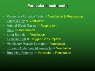
Review SignalProcessing CarrierCircuits Transmission Medium Carrier Circuits SignalProcessing m(t) s(t) r(t) TRANSMITTER CHANNEL RECEIVER Communication Channel • Transmission medium Wireline (twisted pair, coaxial, fiber optics) Wireless (indoor/air, outdoor/air, underwater, space) • Propagating signals degrade over distance • Repeaters can strengthen signal and reduce noise baseband baseband bandpass bandpass baseband baseband
input output CommunicationChannel x(t) y(t) Wireline Channel Impairments • Linear time-invariant effects Attenuation: dependent on channel frequency response Spreading: finite extent of each transmitted pulse increases Tb Th Th+Tb t t -A Th -A Model channel as LTI system with impulse responseh(t) A A Th 1 t Tb t Th Th Th+Tb t Assume that Th < Tb Bit of ‘0’ or ‘1’
Wireline Channel Impairments • Linear time-varying effects Phase jitter: sinusoid at same fixed frequency experiences different phase shifts when passing through channel Visualize phase jitter in periodic waveform by plotting it over one period, superimposing second period on the first, etc. • Nonlinear effects Harmonics: due to quantization, voltage rectifiers, squaring devices, power amplifiers, etc. Additive noise: arises from many sources in transmitter, channel, and receiver (e.g. thermal noise) Additive interference: arises from other systems operating in transmission band (e.g. microwave oven in 2.4 GHz band)
Home Power Line Noise/Interference Measurement taken on a wall power plug in an apartment in Austin, Texas, on March 20, 2011
Home Power Line Noise/Interference Spectrally-ShapedBackground Noise Measurement taken on a wall power plug in an apartment in Austin, Texas, on March 20, 2011
Home Power Line Noise/Interference Narrowband Interference Spectrally-ShapedBackground Noise Measurement taken on a wall power plug in an apartment in Austin, Texas, on March 20, 2011
Home Power Line Noise/Interference Periodic and AsynchronousInterference Narrowband Interference Spectrally-ShapedBackground Noise Measurement taken on a wall power plug in an apartment in Austin, Texas, on March 20, 2011
Wireless Channel Impairments • Same as wireline channel impairments plus others • Fading: multiplicative noise Talking on a mobile phone and reception fades in and out Represented as time-varying gain that follows a particular probability distribution • Simplified channel model for fading, LTI effects and additive noise FIR + noise
Hybrid Communication Systems • Mixed analog and digital signal processing in the transmitter and receiver Example: message signal is digital but broadcast over an analog channel (compressed speech in digital cell phones) • Signal processing in the transmitter • Signal processing in the receiver Error Correcting Codes Digital Signaling A/D Converter D/A Converter m(t) baseband signal A/D Equalizer Detection Decoder Waveform Generator D/A digitalsequence digitalsequence code
Optional p(t) t T Ts T+Ts 2Ts Pulse Amplitude Modulation (PAM) • Amplitude of periodic pulse train is varied with a sampled message signal m(t) Digital PAM: coded pulses of the sampled and quantized message signal are transmitted (lectures 13 and 14) Analog PAM: periodic pulse train with period Ts is the carrier (below) m(t) s(t) = p(t) m(t)
Optional Pulse amplitude varied with amplitude of sampled message Sample message every Ts Hold sample for T seconds (T < Ts) Bandwidth 1/T Transmitted signal h(t) is a rectangular pulseof duration T units s(t) m(0) m(t) h(t) m(Ts) 1 t t T T Ts T+Ts 2Ts Analog PAM sample hold
Transmitted signal Fourier transform Equalization of sample and hold distortion added in transmitter H(f) causes amplitude distortion and delay of T/2 Equalize amplitude distortion by post-filtering with magnitude response Negligible distortion(less than 0.5%) if Optional Analog PAM msampled(t)
Optional Analog PAM • Requires transmitted pulses to Not be significantly corrupted in amplitude Experience roughly uniform delay • Useful in time-division multiplexing public switched telephone network T1 (E1) line time-division multiplexes 24 (32) voice channels Bit rate of 1.544 (2.048) Mbps for duty cycle < 10% • Other analog pulse modulation methods Pulse-duration modulation (PDM),a.k.a. pulse width modulation (PWM) Pulse-position modulation (PPM): usedin some optical pulse modulation systems.