Download
1 / 57
580 likes | 767 Vues
B.Satyanarayana, Department of High Energy Physics. Design and characterisation studies of Resistive Plate Chambers. Plan of the talk. Introduction The INO Iron Calorimeter (ICAL) Principle of operation of RPC Review of RPC detector developments Design and studies of small RPC prototypes

E N D
B.Satyanarayana, Department of High Energy Physics Design and characterisation studies of Resistive Plate Chambers
Plan of the talk • Introduction • The INO Iron Calorimeter (ICAL) • Principle of operation of RPC • Review of RPC detector developments • Design and studies of small RPC prototypes • Development of RPC materials and procedures • Large area RPC development • Construction of ICAL prototype detector • Data analysis and results • Summary and future outlook • Acknowledgements B.Satyanarayana, DHEP November 5, 2008
Introduction RPC R&D was motivated by its choice for INO’s neutrino experiment. B.Satyanarayana, DHEP November 5, 2008
Neutrino () • Proposed by Wolfgang Pauli in 1930 to explain beta decay. • Named by Enrico Fermi in 1931. • Discovered by F.Reines and C.L.Cowan in 1956. • Created during the Big Bang, Supernova, in the Sun , from cosmic rays, in nuclear reactors, in particle accelerators etc. • Interactions involving neutrinos are mediated by the weak force. B.Satyanarayana, DHEP November 5, 2008
Standard model of particle physics <2.2eV <15.5MeV <170keV B.Satyanarayana, DHEP November 5, 2008
Neutrino oscillations • It is now known that neutrinos of one flavour oscillate to those of another flavour. • The oscillation mechanism is possible only if the neutrinos are massive. • Neutrino experiments are setting the stage for extension of Standard Model itself. • Massive neutrinos have ramifications on nuclear physics, astro physics cosmology, geo physics apart from particle physics • Electron and muon neutrinos (e and ) are the flavour eigen states. They are super positions of the mass eigen states (1 and 2).. • If at t = 0, an eigen state (0) = e, then any time t • Then the oscillation probability is • And the oscillation length is B.Satyanarayana, DHEP November 5, 2008
The INOIron Calorimeter (ICAL) India-based Neutrino Observatory (INO) is a consortium of a large number of research centres and universities. B.Satyanarayana, DHEP November 5, 2008
Neutrino physics using ICAL Reconfirm atmospheric neutrino oscillation Improved measurement of oscillation parameters Search for potential matter effect in neutrino oscillation Determining the mass hierarchy using matter effect Study of ultra high energy neutrinos and muons Long baseline target for neutrino factories B.Satyanarayana, DHEP November 5, 2008
Up-Down asymmetry measurement • Atmospheric neutrino energy > 1.3GeV Dm2 ~2-310-3 eV2 • Downward muon neutrino are not affected by oscillation • They may constitute a near reference source • Upward neutrino are instead affected by oscillation since the L/E ratio ranges up to 104 Km/GeV • They may constitute a far source • Thus, oscillation studies with a single detector and two sources B.Satyanarayana, DHEP November 5, 2008
Matter effects andneutrino mass hierarchy • Matter effects help to cleanly determine the sign of the Δm2 • Neutrinos and anti-neutrinos interact differently with matter • ICAL can distinguish this by detecting charge of the produced muons, due to its magnetic field • Helps in model building for neutrino oscillations B.Satyanarayana, DHEP November 5, 2008
Neutrino sources anddetector choice • Source of neutrinos • Use atmospheric neutrinos as source • Need to cover a large L/E range • Large L range • Large E range • Physics driven detector requirements • Should have large target mass (50-100 kT) • Good tracking and energy resolution (tracking calorimeter) • Good directionality (< 1 nSec time resolution) • Charge identification capability (magnetic field) • Modularity and ease of construction • Compliment capabilities of existing and proposed detectors • Use magnetised iron as target mass and RPC as active detector medium B.Satyanarayana, DHEP November 5, 2008
INO cavern: Location and design • Singara, about 105km south of Mysore or about 35km north of Ooty. • About 6km from the TNEB’s PUSHEP established township in Masinagudi. • The INO cavern will be built at about 2.3 km from the INO under ground tunnel portal. • 7,100km from CERN, Geneva – Magic baseline distance! • Wealth of information on the site, geology ,seismicity, and rock quality etc. INO Peak (2203m) B.Satyanarayana, DHEP November 5, 2008
Assembly of ICAL detector 4000m m2000mm56mm low carbon iron slab RPC • 16m × 16m × 14.5m B.Satyanarayana, DHEP November 5, 2008
Principle of operation of RPC Gaseous detector of planar geometry, high resistive electrodes, wire-less signal pickup B.Satyanarayana, DHEP November 5, 2008
Schematic of a basic RPC 3 B.Satyanarayana, DHEP November 5, 2008
Principle of operation • Electron-ion pairs produced in the ionisation process drift in the opposite directions. • All primary electron clusters drift towards the anode plate with velocity v and simultaneously originate avalanches • A cluster is eliminated as soon as it reaches the anode plate • The charge induced on the pickup strips is q = (-eΔxe + eΔxI)/g • The induced current due to a single pair is i = dq/dt = e(v + V)/g ≈ ev/g, V « v • Prompt charge in RPC is dominated by the electron drift B.Satyanarayana, DHEP November 5, 2008
RPC operating mode definitions Let, n0 = No. of electrons in a cluster = Townsend coefficient (No. of ionisations/unit length) = Attachment coefficient (No. of electrons captured by the gas/unit length) Then, the no. of electrons reaching the anode, n = n0e(- )x Where x = Distance between anode and the point where the cluster is produced. Gain of the detector, M = n / n0 • A planar detector with resistive electrodes ≈ Set of independent discharge cells • Expression for the capacitance of a planar condenser Area of such cells is proportional to the total average charge, Q that is produced in the gas gap. Where, d = gap thickness V = Applied voltage 0 = Dielectric constant of the gas • Lower the Q; lower the area of the cell (that is ‘dead’ during a hit) and hence higher the rate handling capability of the RPC B.Satyanarayana, DHEP November 5, 2008
Control of avalanche process • Role of RPC gases in avalanche control • Argon is the ionising gas • R134a to capture free electrons and localise avalanche e- + X X- + h (Electron attachment) X+ + e- X + h (Recombination) • Isobutane to stop photon induced streamers • SF6 for preventing streamer transitions • Growth of the avalanche is governed by dN/dx = αN • The space charge produced by the avalanche shields (at about αx = 20) the applied field and avoids exponential divergence • Townsend equation should be dN/dx = α(E)N B.Satyanarayana, DHEP November 5, 2008
Two modes of RPC operation Avalanche mode Streamer mode • Gain of the detector > 108 • Charge developed ~ 100pC • No need for a preamplier • Relatively shorter life • Typical gas mixture Fr:iB:Ar::62.8:30 • High purity of gases • Low counting rate capability • Gain of the detector << 108 • Charge developed ~1pC • Needs a preamplifier • Longer life • Typical gas mixture Fr:iB:SF6::94.5:4:0.5 • Moderate purity of gases • Higher counting rate capability B.Satyanarayana, DHEP November 5, 2008
V-I characteristics of RPC Glass RPCs have a distinctive and readily understandable current versus voltage relationship. B.Satyanarayana, DHEP November 5, 2008
Typical expected parameters • Gas: 96.7/3/0.3 • Electrode thickness: 2mm • Gas gap: 2mm • Relative permittivity: 10 • Mean free path: 0.104mm • Avg. no. of electrons/cluster: 2.8 • Charge threshold: 0.1pC • HV: 10.0KV • Townsend coefficient: 13.3/mm • Attachment coefficient: 3.5/mm • Efficiency: 90% • Time resolution: 950pS • Total charge: 200pC • Induced charge: 6pC No. of clusters in a distance g follows Poisson distribution with an average of Probability to have n clusters Intrinsic efficiency max depends only on gas and gap Intrinsic time resolution t doesn’t depend on the threshold B.Satyanarayana, DHEP November 5, 2008
Review ofRPC detector developments Creativity aided by intrinsic tunability of the RPC device B.Satyanarayana, DHEP November 5, 2008
Birth of the RPC B.Satyanarayana, DHEP November 5, 2008
Application driven RPC designs Double gap RPC Single gap RPC Multi gap RPC Hybrid RPC Micro RPC B.Satyanarayana, DHEP November 5, 2008
Deployment of RPCs in running experiments Also deployed in COVER_PLASTEX,EAS-TOP, L3 experiments B.Satyanarayana, DHEP November 5, 2008
Design and studies ofsmall RPC prototypes The first RPC built at TIFR was 30cm 10cm! B.Satyanarayana, DHEP November 5, 2008
Initial infrastructure for RPC R&D B.Satyanarayana, DHEP November 5, 2008
Some early encouraging results B.Satyanarayana, DHEP November 5, 2008
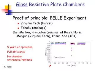
Long-term stability study of RPC • Two RPCs of 40cm × 30cm in size were built using 2mm glass for electrodes • Readout by a common G-10 based signal pickup panel sandwiched between the RPCs • Operated in avalanche mode (R134a: 95.5% and the rest Isobutane) at a high voltage of 9.3KV • Round the clock monitoring of RPC and ambient parameters – temperature, relative humidity and barometric pressure • Were under continuous operation for more than three years • Chamber currents, noise rate, combined efficiencies etc. were stable • Long-term stability of RPCs is thus established Relative humidity Pressure Temperature B.Satyanarayana, DHEP November 5, 2008
Development ofRPC materials and procedures Continuous interaction with local industry and quality control standards B.Satyanarayana, DHEP November 5, 2008
Materials for gas volume fabrication Schematic of an assembled gas volume Edge spacer Gas nozzle Glass spacer B.Satyanarayana, DHEP November 5, 2008
Electrode coating techniques • Graphite paint prepared using colloidal grade graphite powder(3.4gm), lacquer(25gm) and thinner(40ml) • Sprayed on the glass electrodes using an automobile spray gun. • A uniform and stable graphite coat of desired surface resistivity (1M/) was obtained by this method. B.Satyanarayana, DHEP November 5, 2008
Automatic spray paint plant Drive for Y-movement Automatic spray gun Control and drive panel Glass holding tray Drive for X-movement B.Satyanarayana, DHEP November 5, 2008
Screen printing techniques On glass On films B.Satyanarayana, DHEP November 5, 2008
Schematic of gas system B.Satyanarayana, DHEP November 5, 2008
Constructional details ofthe gas system Internal view Front view Rear view B.Satyanarayana, DHEP November 5, 2008
Development and characterisation of signal pickup panels Foam panel 48.2Ω G-10 panel Open 100Ω 51Ω 47Ω Z0: Inject a pulse into the strip; tune the terminating resistance at the far end, until its reflection disappears. Honeycomb panel B.Satyanarayana, DHEP November 5, 2008
Large area RPC development Scaling up dimensions without deterioration of characteristics B.Satyanarayana, DHEP November 5, 2008
Fully assembled large area RPC 1m 1m B.Satyanarayana, DHEP November 5, 2008
RPC parameter characterisation B.Satyanarayana, DHEP November 5, 2008
Construction ofICAL prototype detector Want to check if everything works as per design! B.Satyanarayana, DHEP November 5, 2008
Prototype detector magnet • 13 layer sandwich of 50mm thick low carbon iron (Tata A-grade)plates (35ton absorber) • Detector is magnetised to 1.5Tesla, enabling momentum measurement of 1-10Gev muons produced by μ interactions in the detector. B.Satyanarayana, DHEP November 5, 2008
Prototype RPC stack B.Satyanarayana, DHEP November 5, 2008
Design and implementation of the data acquisition system 200 boards of 13 types Custom designed using FPGA,CPLD,HMC,FIFO,SMD B.Satyanarayana, DHEP November 5, 2008
Data analysis and results Using a ROOT based package BigStackV3.8 B.Satyanarayana, DHEP November 5, 2008
A couple of interesting events B.Satyanarayana, DHEP November 5, 2008
Strip hit map of an RPC B.Satyanarayana, DHEP November 5, 2008
RPC strip rate time profile Temperature B.Satyanarayana, DHEP November 5, 2008
On-line monitoring ofambient parameters Temperature R.H Current B.Satyanarayana, DHEP November 5, 2008
Summary and future outlook RPC: Is it the best thing happened after MWPC? B.Satyanarayana, DHEP November 5, 2008