Download

1 / 32
320 likes | 505 Vues
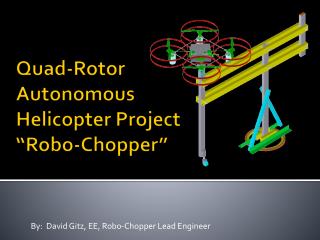
Team Chopper Distributed Communication Nodes for Autonomous Helicopters. Shirley Choi Bejan Hafezzadeh Joseph Kaiser Sean Norwood Itay Tenne. Normal Mode. Inverted Mode. Introduction. Subterranean Mapping Using Wire Suspended by Two Autonomous Co-operative Helicopters. Overview

E N D
Team ChopperDistributed Communication Nodes for Autonomous Helicopters Shirley Choi Bejan Hafezzadeh Joseph Kaiser Sean Norwood Itay Tenne
Normal Mode Inverted Mode Introduction Subterranean Mapping Using Wire Suspended by Two Autonomous Co-operative Helicopters Overview • Topological Avionics Diagram • CAIN PCB (Can Avionics Interface Node) • Block Diagram (all ICs in relative location) • Schematic • Layout • Pictures • JOANN protocol • Key features & Terminology • Abstract CAIN Block Diagram & Unit Example • Comprehensive Example • Part List • Division of Labor • Schedule DeSalvo Tandem
Power Generator Power Board Interface Board Interface Board Interface Board Interface Board Interface Board Interface Board Flight Computer All Boards Topological Diagram Satellites INS Pressure Sensors Magnetometer IMU GPS RS232 RS232 RS232 RS644 RS232 CAN Multi-Drop Bus Interface Board Interface Board Servo Isolation Servo battery RS232 RS232 PWM signals Bluetooth Module On board Radio Servos RC receiver Bluetooth Ground Radio RC Transmitter Host PC for test, debug, and configuration USB USB Error Correcting GPS To GPS
CAIN PCB Block Layout TWI/SPI ADC addr ISP JTAG Addr/data CAN transceiver / CAN bus CAN transceiver / CAN bus NV RAM RS232-0 RS644 Atmel AT90CAN128 LEDs PWM (6 channels) EEPPOM RS232-1 Jumpers/Selectors
CAIN 6-Layer PCB TOP PWR SIG1 SIG2 GND BOTTOM
CAIN Revision 1 Pictures Status • Processor & All peripherals functional • I2C EEPROM untested • NVRAM untested TOP Populated Bottom Populated
Power Distribution Board • Takes AC from the onboard Brushless Alternator • Converts to DC • Regulates the DC it to 5.4Volts D.C. • Converts the 5.4Volts D.C. to many other voltages (+5V,+3.3V,±8.5V) • Will be implemented on a PCB
Power Distribution Board • To be implemented on a Printed Circuit Board • Will use on chip switching converters for high efficiency. • Will use Surface mount chips for low noise and ruggedness.
JOANN Protocol “Jolly Old Avionics Node Networking” (actually named in retribution to JOANN for the shopping cart) Key Features • Generic and Powerful • Easy to use • Conceptually similar to a directed graph • FIFO buffers are pervasively used as sockets • Sockets and Channels are established during initialization. • Kernel runs in background and routes source to destination. • Configurable Real-Time Transit Delays
Terminology • “socket”: a FIFO buffer which is used as a global source or sink, analogous to vertices in a directed graph. • “channel”: a custom struct which holds all information about the channel between two sockets, including the id_path, transit_delay, source and sink pointer, etc., analogous to an edge. • “id_path”: FIFO buffer of multiple IDs linking nodes and sockets. • “port”: a FIFO buffer for low level on-chip external interface (UART, I2C, CAN,PWM_IN, PWM_OUT…) • “node”: one of the physical CAIN PCBs • “FIFO buffer”: First In First Out buffer that passes data along the channel Source Port Sink Port Source Socket Sink Socket Channel
Simple Example Select Devices in config.h • UART1_DEVICE = IMU • UART1_DEVICE = GPS • UART1_DEVICE = PRESSURE • … • PWM_CH_1_DEVICE = SERVO • I2C_DEVICE = EEPROM • … On-Board Ports • UART0 (RS232 or TTL) • UART1 (RS232,RS644 or TTL) • CAN • SPI • I2C • GP I/O & ADC • PWM_CH_m OUT • PWM_CH_n IN dev_m_parser() process_1() get_dev_m_data() or ISR() router() Device_m Port_A s_sock_1 d_sock_1 s_sock_2 Device_n Port_B d_sock_3 s_sock_3 d_sock_2 router() send_dev_m_data() or ISR() process_2() dev_n_dispatcher()
Less simple example IMU BLUETOOTH servo_ch1 servo_ch2 servo_ch3 rcvr_ch1 rcvr_ch2 rcvr_ch3 GPS ELAN 5P servo_ch1 servo_ch2 servo_ch3 rcvr_ch1 rcvr_ch2 rcvr_ch3
Init_ports(); #if UART0_DEVICE == IMU Init_buffer(A,SIZE_A); XRAM_PTR += SIZE_A; //… same for all #endif //attach UART_PORT to IMU SOCKET Init_buffer(B, SIZE_B); Init_buffer(C, SIZE_C); //Channel ID_paths used to connect sockets //could make as many as you want Init_buffer(ID_path, SIZE_PATH); Link_to_ID_path(B); Link_to_ID_path(C); Link_to_ID_path(SERVO1); //last one on path is object ID //Create channel object linking A to SERVO1 //Locally, only a single edge //Globally, a path defined here is propagated. Create_new_channel(A,ID_path); Code Example Mainloop() { router() //Background Kernel #if UART0_DEVICE == IMU imu_service(); #endif //… same for all gps_service(); elan_service(); rcvr_service(); servo_service(); bluetooth_service(); process1(); process2(); process3(); }
Controller Area Network (CAN) • We will use CAN to transmit data between our avionics equipment • CAN is a multicast serial bus standard that allows for high data transfer rates • It allows for priority-based bus arbitration, ideal for our system
Standard CAN Data Frame • The 11 bit identifier field allows for bus arbitration • 4 bit DLC field declares the length of the data packet in the following field • The integrity of the data is protected by a checksum (CRC)
CAN Controller • CAN controller on the AT90CAN128 Microcontroller
To servos RC Demodulation RC Receiver PWM Demodulator PWM Port 41958 2915 31958 28910 9185 5267 21850 9481 42018 CAN Parser / Dispatcher
Servos • Motor with an onboard controller • Gets position Signals and moves to that position • Receives commands via PWM • 5volt supply needed
GPS • NMEA standard • GPGGA sentence identifier • RS232 interface • ASCII messaging format NMEA: Latitude longitude altitude
GPS • Tested the GPS with GPSolution
Flight Box • Isolate vibration from the helicopter • A damper-spring system • Provide shielding for the power board • Designed with Solidworks, analyzed by Ansys • Carbon fiber and aluminum • Will be machined and assemble in ITLL
1 2 3 4 Example: GPS board mounting
Part List Total: $2320 Funded by Prof. Meyer and UROP
Part List Provided by Prof. Meyer:
Division of Labor • Bejan • I2C on chip communication • Node testing routines • Itay • RC demodulation • JOANN development • Joe • Power PCB • Servo driver • Sean • JOANN development • CAIN PCB revision 2 • Shirley • Flight Box • GPS • All • Testing and Debugging
Goals Toward Milestones • Milestone I • Completion of the power board PCB • Completion of the fabrication of the flight box • Completion of the Servo node • Completion of JOANN research development • Milestone II • Fully tested JOANN • System completely interfacing thought CAN bus • Shopping Cart testing
Goals Toward Expo • Completion of CAIN PCB revision 2 • System Identification • Hopefully Hovering!