Download
1 / 18
200 likes | 303 Vues
Learn how to breadboard circuits for OpenPLC using Arduino with detailed instructions on components, hints, and references. Explore cyber-physical systems and electronic platforms.

E N D
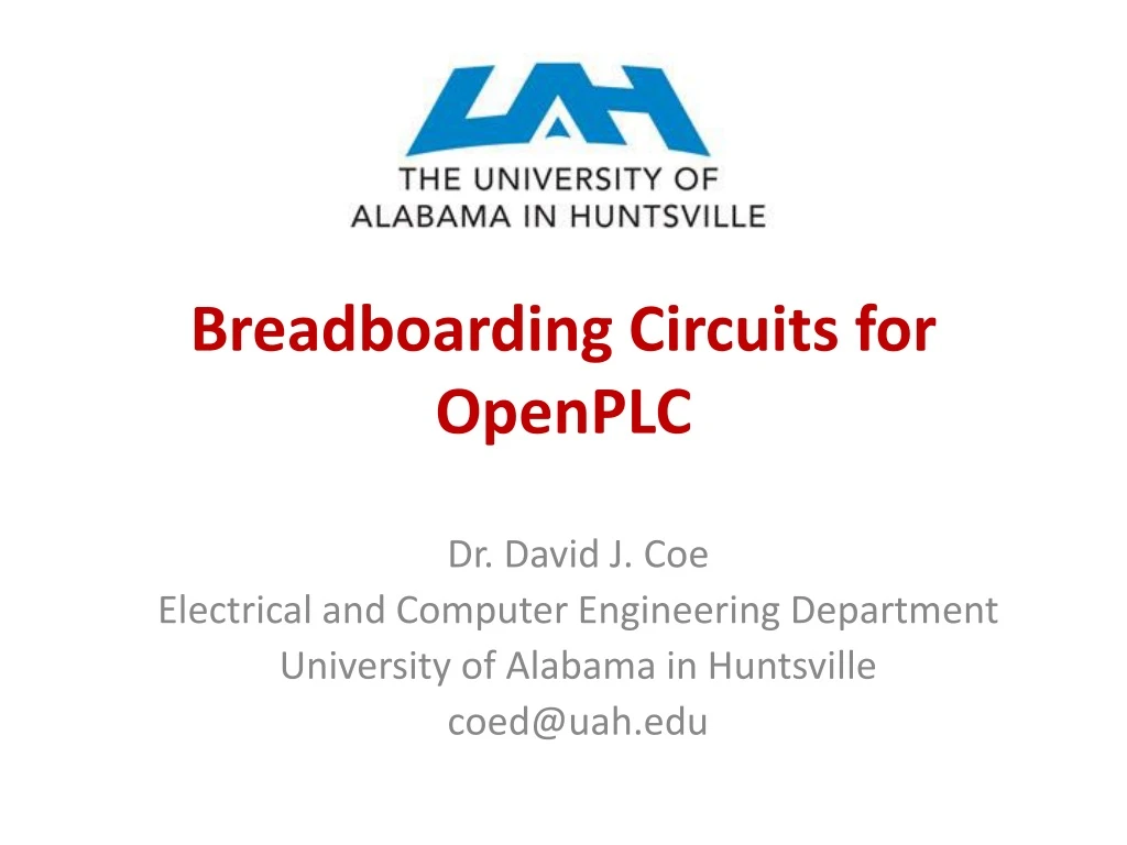
Breadboarding Circuits for OpenPLC Dr. David J. Coe Electrical and Computer Engineering Department University of Alabama in Huntsville coed@uah.edu
Outline • Introduction to Arduino • Arduino-OpenPLC Setup • Breadboarding of Circuits • References
What is an Arduino? • An open source electronics platform for building cyber-physical systems • Cyber-physical systems sense and interact with their surroundings Arduino Uno ~$22 https://store.arduino.cc/usa/arduino-uno-rev3
Arduino Uno R3 Pinout https://www.circuito.io/blog/arduino-uno-pinout/
Arduino Uno R3 – OpenPLC Pinout Slave devices start at 100 so add 100 Example: %IX100.0 https://www.openplcproject.com/getting-started-arduino
Download OpenPLC Firmware for Arduino Uno Download firmware from https://www.openplcproject.com/getting-started-arduino
Circuit Schematic +V PB1 %IX100.0 %QX100.0 OpenPLC Slave Arduino Uno R3 R1 R3 %IX100.1 LED1 R2 PB2 Ground • +V is 5Volts for the Arduino • PB1 and PB2 are momentary pushbuttons • R1 = R2 = R3 = 1 k Ohm resistor • LED1 is a light emitting diode (LED)
Circuit Components – Prototyping Breadboards http://wiring.org.co/learning/tutorials/breadboard/
Cyber-Physical Systems: Circuit Hints • Breadboard your circuit before powering up the Arduino or Raspberry Pi • Check it carefully before applying power • Double check against the pinout diagrams • Be mindful of component voltage levels • Some may be 5V, others 3.3V • Routing 5V into a 3.3V device is usually bad • Level translation may be required • Learn to interpret the component datasheets • Look at min/max voltages and currents • May provide sample circuits that illustrate use of a particular component • Invest in a multimeter for measuring voltages, currents, resistance, and continuity
Cyber-Physical Systems: Circuit Hints • Most processor General Purpose Input/Output (GPIO) pins are not designed to drive low impedance/low resistance loads • Relay, solenoid, and motor coils require a driver circuit that can supply more current than the GPIO pins • LEDs typically require a series resistor to limit current draw • Resistor too large allows too little current flow (dim LED) • Resistor too small or non-existent allows too much current flow (bad) • Failure to limit current sourcing/sinking through GPIO pins may result in permanent damage to the Raspberry Pi (or Arduino) • Relay/solenoid coils may require a parallel diode to dissipate back EMF (current flowing from collapsing magnetic field)
Circuit Components – Resistors - 1 I I + V - + V - Ohm’s Law Voltage = Current x Resistance V = I x R Current calculations for 1k ohm resistor with 5 V and 3.3 V circuits I = V / R = 3.3 volts/1000 ohm = 3.3 milliamps (mA) I = V / R = 5.0 volts/1000 ohm = 5.0 milliamps (mA)
Circuit Components – Resistors - 2 https://sites.google.com/site/kmitl58010166/home/lab-i-basic-resistive-circuit-calculations-and-measurements Photograph of 1 kOhm resistor Sample output from online resistance calculator at URL below https://learn.sparkfun.com/tutorials/resistors
Circuit Components - Diodes Light Emitting Diode (LED) Signal Diode “one-way current check valve” https://cdn.sparkfun.com/assets/learn_tutorials/7/5/backwardsDiode.png https://www.electronics-tutorials.ws/diode/diode_4.html
Circuit Components - Pushbuttons A B A B A B A B Switch Closed (Switch Pressed) Switch Open (Normally Open) https://components101.com/switches/push-button
References • The OpenPLC Project https://www.openplcproject.com/ • Horowitz and Hill, The Art of Electronics 2nd ed. • Good overview of digital and analog circuits with many examples including interfacing to sensors and actuators such as those in a cyber-physical system