Download
1 / 22

E N D
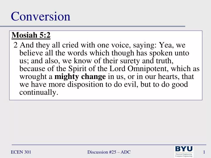
Conversion Mosiah 5:2 2 And they all cried with one voice, saying: Yea, we believe all the words which though has spoken unto us; and also, we know of their surety and truth, because of the Spirit of the Lord Omnipotent, which as wrought a mighty change in us, or in our hearts, that we have more disposition to do evil, but to do good continually. Discussion #25 – ADC
Lecture 25 –Analog to Digital Convertion (ADCs) Discussion #25 – ADC
ADC/DAC • Sensors are generally analog, but most signal processing devices (appliances, computers, etc.) are digital thus there must be a conversion • Analog to digital (ADC) – coming into a device • Digital to analog (DAC) – going out of a device Sensor Actuator Device ADC DAC Analog Analog Digital Discussion #25 – ADC
ADC/DAC • Sensors are generally analog, but most signal processing devices (appliances, computers, etc.) are digital thus there must be a conversion • Analog to digital (ADC) – coming into a device • Digital to analog (DAC) – going out of a device ADC DAC Analog Analog Digital 2.23094… 001110011… 2.23094… Discussion #25 – ADC Discussion #24 – DAC
Analog to Digital Converter (ADC) ADC: converts an analog voltage or current into a binaryword • Binary word (B): a sequence of n 1s and 0s • B = bn-1bn-2…b2b1b0 • EX: • B = 10100101 (n = 8) Note: many ADCs can only convert positive or negative values • Word length (n): the number of bits in the sequence of 1s and 0s representing an output • EX: • 0110 – 4-bit word length • 100101 – 6-bit word length ECEN 301 Discussion #25 – ADC • 5
Analog to Digital Converter (ADC) ADC: converts an analog voltage or current into a binaryword Resolution δv: minimum step size by which the output voltage (or current) can increment • Input voltage va: the analog value represented by the binary word B • EX: let n=4 (number of bits) • va = (23·b3 + 22·b2 + 21·b1 + 20·b0)δv • Example: δv = 1V, B = 10110 (n = 5) • Find vaMax and va • vaMax = (2n – 1)δv • = (25 – 1) ∙ 1 • = 31 • va = (24·b4 + 23·b3 + 22·b2 + 21·b1 + 20·b0)δv • = (16·1 + 8·0 + 4·1 + 2·1 + 1·0) · 1 • = (16 + 4 + 2) • = 22 • Max input voltage vaMax: the maximum analog value • EX: let n=4 (number of bits) • vaMax = (23 + 22 + 21 + 20)δv • = (2n – 1) δv ECEN 301 Discussion #25 – ADC • 6
Positive power supply (+5V) VS+ v+ vinput vo + – v– + – vref VS– Negative power supply (–5V) Op Amp Comparator • An op amp without feedback is a binary comparator • Rail-to-rail output swing • Simple one-bit analog to digital converter Discussion #25 – ADC
Quantized voltage Binary representation • vdb3 b2 b1 b0 • 0 0 0 0 0 • 0 0 0 1 • 0 0 1 0 • 0 0 1 1 • … … • 1 1 1 0 • 1 1 1 1 … 10 8 6 vout (volts) 4 2 0 … 0 2 4 6 8 10 vin (volts) Quantization • Analog representation by a binary value results in quantization of the value Quantization error (vout-vin) always non-positive for this case Discussion #25 – ADC
Quantization (ADC/DAC) Quantization: • The analog output (va) has a step-like appearance because of the discrete nature of a binary signal • The resolution (coarseness of the “staircase”) can be adjusted by changing the word length (the number of bits) Approximated using 2-bits δv δv Approximated using 3-bits Discussion #25 – ADC
+V R vin R – – – – – – vin R + + + + + + RF Rn-1 – Digital logic encoder bn-1 R + + va – Rn-2 bn-2 R R1 b1 R R0 b0 R Digital to Analog Converter (DAC) Comparison of an ADC and DAC Digital output ADC DAC Discussion #25 – ADC
vin + – vref DAC Start conversion Register & Control Logic Clock Conversion complete Digital value output Types of ADCs • Successive approximation • Takes time, input must remain steady during conversion comparator Discussion #25 – ADC
comparator vin – + vref DAC up Up-down counter Clock down Digital value output Types of ADCs • Tracking ADC • Input must remain steady during conversion • Quicker than successive approximation type Discussion #25 – ADC
+V R vin R – – – – – – R + + + + + + Digital logic encoder R R R R Types of ADCs • Flash ADC • Fast (no sample-and-hold required) • Complex • 2N comparators required • Number of bits limited Discussion #25 – ADC
Sample/ hold – – vout + + vin Storage capacitor voltage follower (buffer) voltage follower (buffer) Sample-and-hold • ADC required constant input voltage during conversion. How do we guarantee this? • Use sample-and-hold circuit • Basic idea: store voltage on a capacitor, then hold during conversion • Design caution: capacitor voltage can “droop” during hold Discussion #25 – ADC
Analog to Digital Converter (ADC) Example 1: vin = 4.1V, Vref=5 V, N=4 bits Find Dout and the quantization error Discussion #25 – ADC
Analog multiplexer amplifier Analog in Sample and hold ADC Digital out trigger Clock Control logic Multiplexing • Time share expensive ADC between channels • ADC has to run at higher rate Discussion #25 – ADC
… 10 8 V(t) 6 vout (volts) 4 2 0 0 t … 0 2 4 6 8 10 vin (volts) Time sampling • ADC samples input voltage (generally) at regular intervals • Time and voltage quantization Discussion #25 – ADC
ADC time sampling Ideally, ADC should take signal samples at evenly spaced intervals Can then use discrete Fourier transform (DFT) analysis Sample frequency = 1 / Sample interval Many inexpensive systems use variable spacing This can cause artifacts in measured signals, resulting in reduced accuracy May be OK for signals that change slowly with respect to the sample spacing Discussion #25 – ADC
Nyquist sampling • When measuring a waveform that changes with time, it must be sampled at twice the highest frequency present to avoid aliasing • ADC sampling interval = Ts • ADC sampling frequency = fs = 1/Ts • An analog low pass filter is generally included before the ADC to insure that no signal frequencies are higher than twice the sample rate The Nyquist sampling requirement means that the highest frequency sine wave in the signal has at least two samples per cycle of the sine wave or undesireable aliasing will result. Discussion #25 – ADC
Aliasing • Aliasing occurs when the waveform is undersampled (sampled at too low a frequency). It makes a high frequency signal look like it is a low frequency waveform. • Aliasing should always be avoided. The red waveform is undersampled at 1 Hz. The processor will think the samples (black dots) are from the blue waveform. The red signal is aliased into the blue signal. Discussion #25 – ADC
Sample Frequency Example 1: Ts= 0.001 s What is the highest frequency that can be sampled without aliasing? What is the frequency of the low pass filter that should be included before the ADC? The lowpass filter cutoff frequency should be less than 500 Hz (usually by at least 10%) ECEN 301 Discussion #25 – ADC • 21
Noisy signal vout Vref ΔV vout VS+ v– vout – 0 vin t VS+ vout v+ + VS– 0 t vin VS+ 0 vout Conventional comparator Vref R1 R3 R2 ΔV 0 t VS– Schmitt trigger Schmitt Trigger • Schmitt trigger circuit uses hysteresis to improve noise tolerance Discussion #25 – ADC