Download
1 / 68
690 likes | 909 Vues
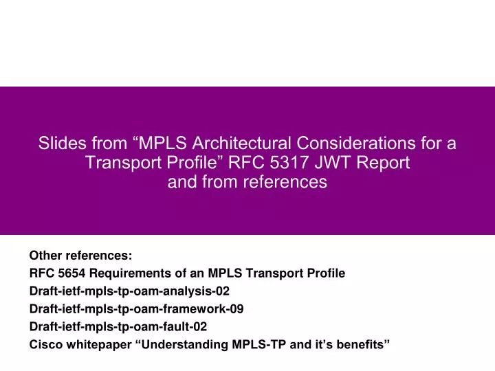
Slides from “MPLS Architectural Considerations for a Transport Profile” RFC 5317 JWT Report and from references. Other references: RFC 5654 Requirements of an MPLS Transport Profile Draft-ietf-mpls-tp-oam-analysis-02 Draft-ietf-mpls-tp-oam-framework-09 Draft-ietf-mpls-tp-oam-fault-02

E N D
Slides from “MPLS Architectural Considerations for a Transport Profile” RFC 5317 JWT Reportand from references Other references: RFC 5654 Requirements of an MPLS Transport Profile Draft-ietf-mpls-tp-oam-analysis-02 Draft-ietf-mpls-tp-oam-framework-09 Draft-ietf-mpls-tp-oam-fault-02 Cisco whitepaper “Understanding MPLS-TP and it’s benefits”
Table of Contents • Executive Overview • Recommendation • Introduction and Background Material • High Level Architecture • OAM Requirements • OAM Mechanisms and Baseline Use Cases • Associated Channel Level (ACH) • Forwarding and OAM • LSP/PW OAM • Use Case Scenario and Label Stack Diagrams • Use of TTL for MIP OAM alert • Control Plane • Survivability • Network Management • Summary
Recommendation • Consensus on recommendation of Option 1 • Jointly agree to work together and bring transport requirements into the IETF and extend IETF MPLS forwarding, OAM, survivability, network management and control plane protocols to meet those requirements through the IETF Standards Process • The Joint Working Team believes this would fulfill the mutual goal of improving the functionality of the transport networks and the internet and guaranteeing complete interoperability and architectural soundness • Refer to the technology as the Transport Profile for MPLS (MPLS-TP) • Therefore, we recommend that future work should focus on: • In the IETF: Definition of the MPLS “Transport Profile” (MPLS-TP) • In the ITU-T: • Integration of MPLS-TP into the transport network • Alignment of the current T-MPLS Recommendations with MPLS-TP and, • Terminate the work on current T-MPLS • The technical feasibility analysis demonstrated there were no “show stopper” issues in the recommendation of Option 1 and that the IETF MPLS and Pseudowire architecture could be extended to support transport functional requirements • Therefore the team believed that there was no need for the analysis of any other option
Development of ITU-T Recommendations on MPLS-TP • The normative definition of the MPLS-TP that supports the ITU-T transport network requirements will be captured in IETF RFCs • The ITU-T will: • Develop Recommendations to allow MPLS-TP to be integrated with current transport equipment and networks • Including in agreement with the IETF, the definition of any ITU-T specific functionality within the MPLS-TP architecture • Via the MPLS change process (RFC 4929) • Revise existing Recommendations to align with MPLS-TP • It is anticipated that following areas will be in scope. The actual Recommendations will be identified by the questions responsible for the topic areas. • Architecture (e.g. G.8110.1) • Equipment (e.g. G.8121) • Protection (e.g. G.8131, G.8132) • OAM (e.g. G.8113, G.8114) • Network management (e.g. G.7710, G.7712, G.8151, …) • Control plane (e.g. G.7713, G.7715, …) • ITU-T Recommendations will make normative references to the appropriate RFCs
What am I reading? • This presentation is a collection of assumptions, discussion points and decisions that the combined group has had during the months of March and April, 2008 • This represents the agreed upon starting point for the technical analysis of the T-MPLS requirements from the ITU-T and the MPLS architecture to meet those requirements • The output of this technical analysis is the recommendation given to SG 15 on how to reply to the IETF’s liaison of July 2007 • IETF requested decision on whether the SDOs work together and extend MPLS aka “option 1: or • ITU-T choose another ethertype and rename T-MPLS to not include the MPLS moniker aka “option 2” • The starting point of the analysis is to attempt to satisfy option 1 by showing the high level architecture, any showstoppers and the design points that would need to be addressed after the decision has been made to work together. • Option 1 was stated as preferred by the IETF and if it can be met; Option 2 will not be explored
Some contributors to this architecture • BT • Verizon • ATT • NTT • Comcast • Acreo AB • Alcatel-Lucent • Cisco • Ericsson • Huawei • Juniper • Nortel • Old Dog Consulting
How is the effort organized? • In ITU-T • TMPLS ad hoc group • In IETF • MPLS interoperability design team • DMZ between the SDOs: Joint Working Team • Segmented into groups looking at • Forwarding • OAM • Protection • Control Plane • Network Management • Goal: Produce a technical analysis showing that MPLS architecture can perform functionality required by a transport profile. • Compare w/ ITU-T requirements and identify showstoppers • Find any obvious design points in MPLS architecture that may need extensions
MPLS - Transport Profile: What are the problems? • Desire to statically configure LSPs and PWEs via the management plane • Not solely via control (routing/signaling) plane • If a control plane is used for configuration of LSPs/PWEs failure and recovery of the control plane must not impact forwarding plane (a la NSR/NSF) • Transport OAM capabilities don’t exist for LSP and PWE independent of configuration mechanism (management plane or GMPLS or PWE control plane) • Full transport FCAPS - AIS, RDI, Connection verification (aka connectivity supervision in G.806), loss of connectivity (aka continuity supervision in G.806), support of MCC and SCC etc • Recent drafts to IETF demonstrate some issues • Service Providers are requesting consistent OAM capabilities for multi-layered network and interworking of the different layers/technologies (L2, PWE, LSP) • Include functionality of Y.1711 and Y.1731 into one architecture
MPLS -TP: What are the problems? What the SP wants! • Service Providers want to be able to offer MPLS LSPs and PWEs as a part of their transport offerings and not just associated with higher level services (e.g. VPNs) • Service Providers want LSPs/PWEs to be able to be managed at the different nested levels seamlessly (path, segment, multiple segments) • aka Tandem Connection Monitoring (TCM), this is used for example when a LSP/PWE crosses multiple administrations • Service Providers want additional protection mechanisms or clear statements on how typical “transport” protection switching designs can be met by the MPLS architecture • Service Providers are requesting that OAM and traffic are congruent • Including scenarios of LAG or ECMP • Or create LSP/PWEs that don’t traverse links with LAG/ECMP
MPLS - TP Requirements Overview • Meet functional requirements stated earlier by service providers • No modification to MPLS forwarding architecture • Solution Based on existing Pseudo-wire and LSP constructs • Bi-directional congruent p2p LSPs • No LSP merging (e.g. no use of LDP mp2p signaling in order to avoid losing LSP head-end information) • Multicast is point to multipoint not MP2MP
MPLS - TP Requirements Overview .2 • OAM function responsible for monitoring the LSP/PWE • Initiates path recovery actions • IP forwarding is not required to support of OAM or data packets • OOB management network running IP is outside scope of feasibility study • Can be used with static provisioning systems or with control plane • With static provisioning, no dependency on routing or signaling (e.g. GMPLS or, IGP, RSVP, BGP, LDP) • Mechanisms and capabilities must be able to interoperate with existing MPLS and PWE control and forwarding planes
MPLS-TP Major Solution Constructs NOTE: These two constructs were used as the basis for the Technical Feasibility study performed by the ad hoc team, JWT and IETF MPLS Interoperability Design Team • Definition of MPLS-TP alert label (TAL) and a Generic Associated Channel (GE ACH) Allows OAM packets to be directed to an intermediated node on a LSP/PWE Via label stacking or proper TTL setting Define a new reserved label (13 is suggested): It is believed that Label 14 cannot be reused at this point • Generic Associated Channel (GE ACH) functionality supports the FCAPS functions by carrying OAM, APS, ECC etc. packets across the network Use of PWE-3 Associated Channel to carry OAM packets GE ACH are codepoints from PWE ACH space but, not necessarily, for PWE purposes GE ACH would be present for OAM of all LSPs
Generic Associated Channel • The OAM msgs are transported through the same data paths to support FCAPS • Fault, Configuration, Accounting, Performance and Security functions • It implies that OAM monitors PW and LSPs • The G-ACH is used in both PWs and LSPs, while the GAL is used to flag the G-ACH in MPLS-TP LSPs.
Associated Channel Level ACH: Overview • Generalised mechanism for carrying management / OAM information • OAM capabilities : Connectivity Checks (CC) and “Connectivity Verification” (CV) • Management information: Embedded Control Channel (ECC) • To support the Data Communications Network (DCN) and the Signalling Communication Network (SCN) – see G.7712 • APS information • Associated Channel Capabilities • Multiple channels can exist between end points • Channel Type Indicates what protocol that is carried • To service an MPLS-TP network new channel types will need to be defined • Management and Control Plane Information (DCN and SCN connectivity) • Via ECC where IP is not configured • Generic ACH contains a “channel Type” field • Need for a registry of protocols • This needs to be blocked for different functions • (IP-Free BFD is currently 7) • We may want to define a vendor specific and experimental range No Showstoppers found
MPLS-TP Major Solution Observations • Bringing ACH functionality into LSPs begins to blur the architectural line between an MPLS LSP and an MPLS Pseudowire The functional differences between an MPLS LSP and MPLS PW must be retained in the architecture • The same OAM mechanism (e.g. ACH) can be unified for LSPs and PWE Enabling the same functionality for both and ease of implementation Avoid breaking anything (e.g. ECMP) There may be specific differences that are discovered in design phase ACH functionality for LSPs should be limited to only OAM, APS & ECC management channel data • A great deal of IETF protocol, design and architectural reuse can be employed to solve the requirements No fundamental change to the IETF MPLS architecture was found to be necessary
MPLS-TP can be regarded as a subset of MPLS. The TP encompasses the maintenance operation (service and operation) of existing transport networks. 1- MPLS does not satisfy the requirements of maintenance operation level in the transport network, despite the fault detection tools (Virtual Circuit Connectivity Verification, Bidirectional Forwarding Detection and LSP-Ping) 2- PHP, LAG and ECMP are turned-off as they introduce the lack the tracebility which makes difficult the management of a connection-oriented path. 3- In MPLS the paths are controlled by the control plane in a soft state which implies that a fault in the control plane will have negative impact on user traffic even if there is no problem in the transport plane. In MPLS-TP the management plane is responsible for the path management and operators can manually manage the paths.
MPLS-TP Main Characteristics (1) MPLS-TP is : 1- Strictly connection-oriented 2- Client-agnostic (Can carry L1, L2, L3 services) 3- Physical layer agnostic 4- Provides strong OAM functions as those provided in transport/carrier networks. These OAM functions are integral part of the MPLS-TP data plane and independent of the control plane.
MPLS-TP Main Characteristics (2) 5- It provides several protection schemes at the data plane similar to those available in traditional optical transport network. 6- Allows network provisioning via a centralized NMS and/or a distributed control plane. 7- The GMPLS control plane is also applicable to the MPLS-TP client or server layers allowing a common approach for management and control of multi-layer transport networks. 8- The control plane does not make NMS obsolete. The NMS needs to configure the control plane and interact with it for connection management.
Static provisioning and dynamic control plane Requirements state that the solution must include static only provisioning Any dynamic Control plane will be based on IETF solutions (GMPLS, IP/MPLS) Control Plane responsible for: End to End, Segment LSPs and PWE-3 application labels (programming the LFIB) Determining and defining primary and backup paths Configuring the OAM function along the path Others : Defining the UNI etc OAM responsible for monitoring and driving switches between primary and backup paths for the end to end path and path segments MPLS+TP Static Provisioning Network Management System Control Plane for PT2PT services OAM OAM OAM Forwarding Tables Edge Forwarding Tables Forwarding Tables Edge
MPLS Transport Profile - Terminology Emulated Service Pseudo-wire Multi-node PSN cloud • Definition of an MPLS Transport Profile (TP) within IETF MPLS standards • Based on PWE3 and LSP forwarding architecture • IETF MPLS architecture concepts • The major construct of the transport profile for MPLS are LSPs • PW are a client layer Attachment Circuit Attachment Circuit CE1 CE2 PE1 PE2 PW1
MEP MEP MEP MEP LSP example - end to end and per carrier monitoring PE PE Carrier 1 Carrier 2 PE P P P PE PE PE NNI NNI NNI end to end LSP OAM MEP MIP MIP MIP MIP MEP segment LSP OAM (inter carrier) segment LSP OAM (carrier 1) segment LSP OAM (carrier 2) MEP MIP MIP MIP MEP • A segment is between MEPs • OAM is end to end or per segment • In SDH/OTN and Ethernet segment OAM is implemented using Tandem Connection Monitoring (TCM) • The OAM in each segment is independent of any other segment • Recovery actions (Protection or restoration) are always between MEPs i.e. per segment or end to end MEP: Maintenance End Point MIP: Maintenance Intermediate Point Note: A policing function (traffic management/shaping) is normally co located with a MEP at a business boundary (UNI/NNI)
Bidirectional Paths • External Static Provisioning • NMS responsible for configuration and ensuring bi-direction congruency • If Dynamic Control Plane • GMPLS bidirectional RSVP for LSP path establishment
OAM Requirements • Must be able to monitor LSP, PWE3 • Inter layer fault correlation • Failure indication propagation across multiple segments • Monitoring of Physical layer, layer 1, layer 2 is out of scope • Packet loss rather than bit error based measurements/metrics for L2, LSP, PWE3 • Per segment (aka tandem connection) and end to end • Fault detection/isolation • Recovery - protection switch or restoration • A security architecture
What is segment recovery? End to End Protection • End to End recovery: • Fault detection and recovery of the end to end pseudo-wire • Fault detection and recovery of the end to end LSP Segment recovery: • Fault detection and recovery of a segment • The recovery mechanism used in a segment is independent of other segments • Segment constructs • Hierarchical nested LSP: Existing construct • MS-PW segment: Currently defined construct in PWE3 • Stacked TCM label (mapped 1:1 with corresponding LSP/PW) A B C D E F Segment Protection
Node identification • Will need to work through identification requirements • What about algorithmically derived label from the IP identifier • What IP identifier if we do not need IP to support forwarding or OAM? • Need to be able to rearrange the DCC without disturbing the forwarding/OAM? A node has multiple identifiers including the following: • Management identifier – normally user friendly, based on the location • MEP/MIP identifier • DCC address - how do management messages reach this node • Control plane identifiers - how are the various control components identified • Forwarding plane identifier - end points and intermediate points - e.g. NNIs These are design issues, no “show stoppers” found
MPLS-TP OAM tool set Taken from “MPLS-TP – The New Technology for Packet Transport Networks¨’ Dieter Beller, Rolf Sperber «The fundamental idea is that dedicated OAM packets are interspersed into the associated user traffic flows».
A B C D E F Overview: OAM hierarchy and mechanisms • L0/L1 : Loss of Light; G.709, SONET/SDH LoS, LoF, ES, SES (NOT DISCUSSED) • Non MPLS L2 connectivity : Native L2 solution 802.1ag (Not Discussed) , Non IP BFD • Failure propagation across layers is supported by this architecture • General LSPs : Generic Exception Label and Generic Associated Channel • Includes End to End and segment LSPs • Used to carry a variety of OAM, Mgmt, signalling protocols. • Pseudo-wires : PWE3 Associated Channel L1/L2 L1/L2 L1/L2 L1/L2 L1/L2 Segment LSP Midpoint End to End LSP Pseudo-wire
MEP MEP LSP monitoring example - monitoring within carrier 1 Carrier 1 Region 1 Region 2 PE PE PE P PE P PE PE NNI INNI NNI end to end LSP OAM MEP MIP MIP MIP segment LSP OAM (inter carrier) Carrier 1 LSP OAM segment MEP MEP MIP MIP carrier 1 region 1 LSP OAM segment carrier 1 region 2 LSP OAM segment MEP MEP MEP MIP MIP MEP • 3 LSP OAM levels + PW OAM • end to end LSP + 2 nested segment LSP levels(Carrier 1 + regions 1/2) • Nested segments are supported by Tandem Connection Monitoring (TCM) in SDH/OTN and Y.1731
Sk Sk Sk MEP MIP Trail Carrier 1 example MEPs/MIPs relationships MEL x: Carrier 1 Carrier 1 LSP segment OAM So Pushing a new label at the MEP So starts a server layer trail that is terminated when the label is removed at the MEP Sk MIP[1] verifies MEPx_So connectivity to MEPy_Sk MIP[2] verifies MEPx_So connectivity to MEPz_So MIP [1] MIP [2] MEL y: Carrier 1, Region 1 MEL z: Carrier 1,Region 2 region 2 OAM region 1 OAM So So • A MIP must support monitoring on the ingress port (logically before the label swap) • An implementation may optionally support a second MIP to monitor the egress port • How will this MIP be addressed
MEP MEP MEP MEP PW over LSP monitoring example CE CE Attachment circuit Attachment circuit Carrier 1 Carrier 2 PE P P P PE PE PE UNI NNI UNI PW OAM (end to end no switching) MEP MEP end to end LSP OAM MEP MIP MIP MEP segment LSP OAM (inter carrier) segment LSP OAM (carrier 1) segment LSP OAM (carrier 2) MEP MIP MIP MIP MEP • end to end LSP OAM is used since PW OAM cannot create MIPs at the inter carrier boundary without a PW switching function MEP: Maintenance End Point MIP: Maintenance Intermediate Point Note: A policing function (traffic management/shaping) is normally co located with a MEP at a business boundary (UNI/NNI)
MEP MEP MEP MEP PW over LSP example with PW switching CE CE Attachment circuit Attachment circuit Carrier 1 Carrier 2 PE P P P PE PE-S PE-S UNI NNI UNI end to end PW OAM (with PW switching) MEP MIP MIP MEP segment LSP OAM (inter carrier) segment LSP OAM (carrier 1) segment LSP OAM (carrier 2) MEP MIP MIP MIP MEP • end to end LSP OAM is not requires since the PW switching points can support a MIP MEP: Maintenance End Point MIP: Maintenance Intermediate Point Note: A policing function (traffic management/shaping) is normally co located with a MEP at a business boundary (UNI/NNI)
LSP monitoring and alarming Generic Exception Label and Generic Associated Channel Proposal • Assign a Transport Alert Label as a Label For yoU (LFU) from reserved label space: • Label 13 has been proposed because, • Label 14 has been allocated to Y.1711 • Y.1711 arch fits within “ACH” architecture • Bottom of Stack is always set on LFU in the transport profile • Define a Generic Associated Channel function • Similar to the PWE-3 Associated Channel but doesn’t have to be associated with a PW • Important the first nibble tells system not to load balance (so not 06 or 04) • Generic Associated Channel is always under a Generic Exception Label if endpoint (MEP) • Generalised Associated Channel defines what packet function using “channel type” field • Examples : What OAM function is carried, DCC, etc LFU/BoS L2 MAC Header L1 Generic ACH Channel payload 0001 | Ver | Resv | Channel Type
Pseudo-wire monitoring and alarmingPWE-3 Control Word and PW-Associated Channel PWL/BOS L2 MAC Header L1 Control Word Payload 0000 | Flags | FRG | Length | Seq # PWL/BOS L2 MAC Header L1 PWE-3 ACH Channel payload 0001 | Ver | Resv | Channel Type This is a representation of what is in RFC 4385
Required Functionality demarked by Associated Channel • CV : Connectivity Verification (detection of configuration errors) • PM: Performance of the path • AIS: Alarm suppression • CC : Continuity Check : Is the path present (may reuse vanilla BFD here) • Light weight • Role is as a CC protocol, it is not a CV protocol • Not a connectivity verification protocol • VCCV-BFD provides capabilities over pseudo-wire • ECC • OSS and control plane communication • APS • Protection switching coordination • Accounting/Billing information • Security exchange • Extra codepoint space to define new or use existing protocols for other functions
Associated Channel Functionality Observations • Existing MPLS LSP OAM uses an IP based control channel and could be used for some OAM functions in transport networks • e.g. CC/CV • The new Alert label based control channel should be able to co-exist with the existing MPLS LSP OAM functions and protocols • OAM message formats and protocol details carried in the OAM channel will be discussed in the design phase • We must figure out what the OAM messages/protocols should be used for the new requirements • Decide whether LSP-Ping or BFD can or should be tweaked or not
Scope of next slides • Slides cover on MEP to MEP and MEP to MIP monitoring • Detailed OAM packet walkthrough not yet covered in this slide-set • For MIP monitoring traceroute or loopback is executed and TTL set accordingly • Introduce concept of LSP/PW TCM label: • This is a label to indicate a tandem monitoring session context • Label is stacked above label of LSP or PW being monitored • 1 for 1 mapping between an LSP / PW and its TCM session. i.e. no multiplexing • Need mechanism to bind TCM label to underlying LSP or PW being monitored • MEP to MIP • MEP sets the TTL of the LSP, TCM or PW label so that it will expire when the target MIP is reached • PHP No Showstoppers found
Color Conventions LSP tandem OAM label LSP label PW tandem OAM label PW label PW control word Label For yoU ACH Notation and color conventions • [Destination][(using label provided by)][optionalFEC]/[StackBit] • Thus D(E)/0 means Destination is D, using label provided by (E) - i.e. c is the tunnel next hop and the Sbit is 0 - i.e. not bottom of stack. • Thus E(E)p/1 means Destination is E, using label provided by (E) the FEC is a pseudowire and the Sbit is 1, i.e. bottom of stack • Special Labels and terms LFU = Label For yoU - OAM alert label Ach = Associated Channel Header CW = Control Word P = PW FEC
Procedural Ordering Overview • Step 1 : establish the segment LSP • Question : can segment LSP and existing end-to-end LSP share bandwidth? • Step 2 : establish a new end-to-end LSP and which must be tunnelled in the segment LSP • Use MBB procedures (for sharing resources between existing and new end-to-end LSP). • Step 3 : Perform switchover after Resv is received in A • ITU-T mechanisms rely on the creation of a Protection Group between the old and new (tunnelled) end-to-end LSP, the forcing of protection switching via APS and the tearing down of the Protection Group • Step 4 : Tear down the old end-to-end LSP
SS-PW over intra-domain LSPLSP, TCM-LSP & PW OAM LFU – Label For You (label 13) ACh – Associated Channel CW – Control Word A B C D E P P P PE PE TCM LSP label does not represent a true LSP No LSP Mux (1:1 mapping) Section OAM LFU/1 LFU/1 LFU/1 LFU/1 ACh ACh ACh ACh TCM-LSP OAM D(C)/0 D(D)/0 LFU/1 LFU/1 ACh ACh E2E (A to E) LSP OAM D(C)/0 D(D)/0 E(B)/0 E(D)/0 E(D)/0 E(E)/0 LFU/1 LFU/1 LFU/1 LFU/1 ACh ACh ACh ACh E2E (A to E) PW OAM D(C)/0 D(D)/0 E(B)/0 E(D)/0 E(D)/0 E(E)/0 E(E)p/1 E(E)p/1 E(E)p/1 E(E)p/1 ACh ACh ACh ACh Non OAM Data Frames TCM-LSPs D(C)/0 D(D)/0 E2E LSP E(B)/0 E(D)/0 E(D)/0 E(E)/0 SS-PW E(E)p/1 E(E)p/1 E(E)p/1 E(E)p/1 CW CW CW CW
LFU – Label For You (label 13) ACh – Associated Channel CW – Control Word SS-PW over inter-provider LSPLSP, TCM-LSP & PW OAM PB = Provider Border LSR Provider A Provider B A B C D E F P PE PB P PB PE Section OAM LFU/1 LFU/1 LFU/1 LFU/1 LFU/1 ACh ACh ACh ACh ACh One hop TCM-LSP OAM and Section OAM would not usually run concurrently TCM-LSP OAM C(B)0 C(C)/0 F(E)/0 F(F)/0 LFU/1 LFU/1 LFU/1 LFU/1 ACh ACh ACh ACh LSPs stitched in C and D E2E LSP OAM C(B)0 C(C)/0 F(E)/0 F(F)/0 C(C)/0 C(C)/0 D(D)/0 F(F)/0 F(F)/0 LFU/1 LFU/1 LFU/1 LFU/1 LFU/1 ACh ACh ACh ACh ACh From DP perspective, LSP stitching is a normal label swap operation E2E PW OAM C(B)0 C(C)/0 F(E)/0 F(F)/0 C(C)/0 C(C)/0 D(D)/0 F(F)/0 F(F)/0 F(F)p/1 F(F)p/1 F(F)p/1 F(F)p/1 F(F)p/1 ACh ACh ACh ACh ACh Non OAM Data Frames TCM-LSPs C(B)0 C(C)/0 F(E)/0 F(F)/0 E2E LSP C(C)/0 C(C)/0 D(D)/0 F(F)/0 F(F)/0 SS-PW F(F)p/1 F(F)p/1 F(F)p/1 F(F)p/1 F(F)p/1 CW CW CW CW CW
MEP to MIP OAM:TTL Processing for PWs and LSPs • In order to maintain individual levels of OAM and path detection • Use pipe model per label level • TTL is not copied up the stack on a push • TTL is not copied down the stack on a pop • TTL is decremented on each swap and pop action • Traceroute for a level can be used to trap packets at each node that processes the label for that level in the label stack • Scenarios to be added: • LSP on FRR path (both facility and detour) • b) PW with ACH processing (no need for LFU, so processing steps are slightly different from LSP processing)
Short Pipe Model with Nested TTL and No PHP Processing A B C D E F G H From the TTL perspective, the treatment for a Pipe Model LSP is identical to the Short Pipe Model without PHP (RFC3443). PW LSP3 LSP2 LSP1 TTL=n TTL=n-1 Stack going into pipe TTL=m TTL=m-1 TTL=m-1 TTL=m-2 Stack received at H TTL=k TTL=k-1 TTL=k-2 TTL=k-2 TTL=k-2 TTL=k-2 TTL=k-3 TTL=k-3 TTL=j TTL=j TTL=j TTL=j TTL=j TTL=j TTL=j TTL=j Bottom of stack