Download
1 / 26
280 likes | 433 Vues
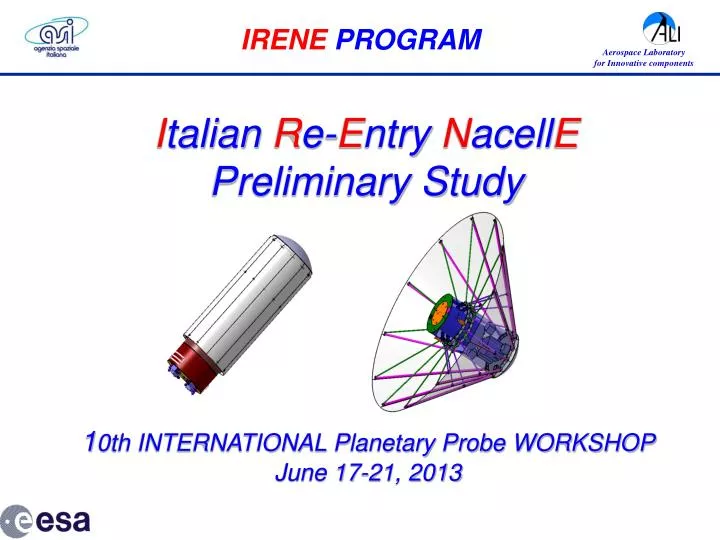
IRENE PROGRAM. I talian R e- E ntry N acell E Preliminary Study. 1 0th INTERNATIONAL Planetary Probe WORKSHOP June 17-21, 2013. BACKGROUND OF THE ACTIVITY (1/2).

E N D
IRENEPROGRAM Italian Re-Entry NacellE Preliminary Study 10th INTERNATIONAL Planetary Probe WORKSHOPJune 17-21, 2013
BACKGROUND OF THE ACTIVITY (1/2) The Italian Space Agency (ASI) is supporting since 2010 a research programme, called IRENE, in Campania (ALI, South of Italy), to develop a low-cost re-entry capsule, able to return payloads from the ISS to Earth and/or to perform short-duration, scientific missions in Low Earth Orbit (LEO). • The main features of the IRENE capsule are: • • light weight (100-200 kg), 3 m fully deployed • • payload recoverability and reusability • • a low-cost, deployable, disposable heat shield composed by: • a fixed nose (made by ceramic or other equivalent TPS) • a deployable aero-brake (umbrella-like, made by special multi-layered fabric). ALI - Aerospace Laboratory for Innovative components is as a Consortium of17 Companies operating within the fields of design, engineering, prototyping and realization of innovative aerospace sybsystems and Ground Segment for technological and scientific platforms
BACKGROUND OF THE ACTIVITY (2/2) The feasibility study of this deployable re-entry system has been carried out in 2011. The TPS materials, selected for the nose cone and for the flexible umbrella shield, have preliminarily been tested in the SPES hypersonic wind tunnel at the University of Naples, and in the SCIROCCO PWT (Plasma Wind Tunnel) at CIRA (Centro Italiano Ricerche Aerospaziali) of Capua, Italy. IRENE TPS test in the SCIROCCO Plasma Wind Tunnel at CIRA
MINI-IRENE DEMONSTRATOR (1/2) • On the basis of the previous results, ESA supported a six months "Bridging Phase” to preliminarily address the main issues of a MINI-IRENE demonstrator to be embarked as a piggy-back payload for a future mission of a sub-orbital MAXUS sounding rocket. • The Mini-IRENE system shall be boarded as a secondary payload in the inter-stage adapter of the rocket and ejected, at an altitude of about 150 km, to perform 15 minutes ballistic flight. • A possible launch of a demonstrator of IRENE from a sounding rocket will require scaling down the most important parameters
MINI-IRENE DEMONSTRATOR (2/2) • Considering a cylindrical volume available with D=29 cm, h=25 cm, mass≈15-20 kg, the following issues have been addressed: • Analysis of the time profiles of the different physical parameters of interest (e.g. pressure, temperature, acceleration). • Preliminary aerodynamic and aero-thermodynamic analysis (engineering methods and CFD analysis of 45 and 60 deg half cone) • Identification of the main mission requirements and corresponding subsystems • Trade-off between different configurations and identification of possible solutions for the different subsystems.
AEROTHERMODYNAMIC ANALYSIS same length of the poles Altitudeversustime Acceleration versus time Altitude versus stagnation pressure Pressure distributions at maximum dynamic pressure condition (left: maximum 21 kPa, right: maximum 10.5 kPa) Main geometric and aerodynamic characteristics
MINI-IRENE REQUIREMENTS • Compatibility with MAXUS inter-stage • Maximum diameters of 29cm (folded) 100cm (deployed) • Total mass below 20 kg / Ballistic coefficient less than or equal to 18 kg/m • Deployable heat shield • Attitude correction before deployment • Automatic system for TPS deployment (during exo-atmospheric phase) generating a 45-60 deg sphere-cone shape • Structure able to withstand mechanical loads at launch and aerodynamic loads during reentry (10000 Pa stagnation pressure, 40g deceleration, impact loads at landing with a velocity in the order of 20 m/s) • TPS able to withstand heat fluxes in the order of 350 kW/m2 • CoG location to guarantee stability and reduce trim angle
PRELIMINARY DESIGN OF THE SUPPORTING STRUCTURE • Three possible solutions have been considered for the supporting structure: • Telescopic poles • Folded arms • Hinged arcs • Any of the solutions foresees upper and lower threads to give rigidity to the whole system and a mobile structure (≈ Tensegrity) • Sufficient room, within the dedicated Maxus volume, is left for the TPS fabrics that must stay properly bended before the deployment • In the present preliminary design all constructions includes a series of 12 main elements (poles, arms or arcs) but this number may vary
Solution 1: 12 telescopic poles • Poles hinged to sliding structure • Upper threads anchored to fixed structure • Lower threads anchored to sliding structure Nose (ceramic) TPS Fixed structure Sliding structure Upper threads Multi layer TPS fabric Closed telescopic poles Elongated telescopic poles Lower threads a1) folded structure; b1) pole elongation phase; c1) tensioning phase
Solution 2: 12 foldable arms • Arms hinged to fixed structure • Upper threads anchored to fixed structure • Lower threads anchored to sliding structure Fixed structure Sliding structure Two-segment foldable arms Upper threads Lower threads a2) folded structure; b2) arm extension phase; c2) tensioning phase
Solution 3: hinged arcs • Arcs hinged one another • Upper threads anchored to fixed structure • Lower threads anchored to sliding structure Double Universal joints Sliding structure Fixed structure Bended arcs of ring Upper threads Lower threads a3) folded structure; b3) rim extension phase; c3) tensioning phase Example of double universal joints. Similar joints could be used to connect the elastic arcs of the ring
TPS PRELIMINARY DESIGN The TPS will be composed by two main sections: - a rigid nose - a flexible part, to be deployed prior to re-entry. The flexible part of the heat shield is not requested to function much as a thermal insulator but, rather, mainly as an aero-brake. The deployable part of the thermal shield should be sufficiently thin and flexible for an easy deployment. It will be necessary to prove that the exposure of the proposed materials to the typical heat fluxes expected during descent would not compromise the tensile strength of the flexible part of the heat shield.
PRELIMINARY DESIGN OF DEPLOYMENT MECHANISM (1/2) • Two different mechanisms have been considered to deploy the IRENE aerobrake/heat shield: • Mechanism #1: Including actuator springs and gas dampers • Mechanism #2: Including a gas actuator Description of Deployment Mechanism #1 This solution exploits harmonic steel compression springs that, once loaded, store the needed mechanical energy to perform the heat shield deployment. In order to avoid abrupt elongation of springs as they are unlocked, a damping system has been devised. Description of Deployment Mechanism #2 The second deployment mechanism which has been devised in this preliminary study exploits a high-pressure gas working as an actuator spring upon a liquid that performs the displacement. In facts, the gas is initially contained in a bottle, under high pressure (not much differently from the gas reservoirs of compressed air guns).
PRELIMINARY DESIGN OF DEPLOYMENT MECHANISM (2/2) View of the heat-shield structure after the deployment mechanisms have been operated (solution 1: telescopic poles)
STRUCTURAL ANALYSIS • A FEM structural analyses has been performed for each of the three identified solutions. The main goal of the activities is the evaluation of the stability and the stress levels in the most critical components of the three solutions. The components so identified, are as follows: • Poles (sol. #1), arms (Sol. #2) and arcs (Sol. #3); • Threads • TPS Fabric layers (FEM models, four layers of NEXTEL AF-10, thickness=0.39 mm). • Results: admissible stress levels for the structural components (considering also the operating temperature) is the following: • Titanium structure 400 MPa at 400°C • NEXTEL Fabric : 40 MPa at 900 °C
SOLUTION SELECTION The solution #1 (with 45 deg half cone) shows a better behavior for the following aspects: • Better aerodynamic stability, due to smaller cone angle (45° instead of 60°) • Largest diameter of the deployed structure due to the deploying mechanism kinematics • Better fabric tension distribution after the deployment phase due to deploying mechanism kinematics • Lower fabric deflection under the re-entry pressure loads
INSTRUMENTATION The most important parameters to be quantified during the re-entry are the aerothermodynamic loads, represented by the surface pressure distribution and the surface heat flux. The main assumption is that the payload consists only of the following sensing elements and their respective data acquisition and storage electronics and power supply: • Thermocouples • Pressure transducers • Linear and angular acceleration sensors • Strain gages • Telecommunications subsystem • On Board Camera and Sound Recording • On Board Data Handling
INSTRUMENTATION: THERMOCOUPLES Sensors: thermocouples location • 2-3 thermocouples at the stagnation point at different depth • 2 thermocouples embedded in outer positions of the nose cone • 3 thermocouples at different positions of the flexible shield, (embedded in the last inner textile layers). • 3 thermocouples located out of the capsule body, and 2 inside the payload area • 3 thermocouple will monitor the ribs heating.
INSTRUMENTATION: PRESSURE SENSORS Sensors: pressure sensors location • 3 pressure sensors embedded at the stagnation point and in (2) outer positions of the nose cone. • 2 pressure sensors located at different positions out of the capsule body, inside the “cone area”. • 2 pressure sensors located on the back shield of the capsule body.
TELECOMUNICATION • No telemetry • A beacon system will be used for the recovery after landing • The beacon shall be operational before landing • The beacon shall be operational after a landing for at least 48hours • The use of standard call and Search and Rescue system, such as Cospas-Sarsat, is allowed • The baseline configuration is “integrated Beacon with antenna out of back TPS” • Trade-off compared and help to select COTS beacon. • Main issues are: • Small and light equipment. • Crushability requirements are critical, in order to avoid previous “Shark mission” impact problems • Power autonomy for at least 48hours
GNC • To acquiring flight parameters and reconstructing flight trajectory of the capsule • Acceleration requirement of a minimum of 40g, (maximum re-entry Acceleration) • Detection of linear and rotation rate of acceleration • Minimize mass and weight • Trade-off compared and help to select the GNC equipment that better match mission requirements. Two different options: • Individual accelerometers and gyroscopes selectedindependently (no IMU) (best solution: solution n. 2 is not readily usable because of the difficulty of interfacing with the OBDH system selected). • Integrated IMU with an acceleration range of more than 40g
ON BOARD DATA HANDLING • The Vehicle Memory Unit (VMU) is one of the most critical part of the mission: it will store all data and has to survive the crash-landing. • Two design possibilities have been evaluated: • Embed the VMU in the Data Handling System. DHS can provide sufficient memory to allocate the whole mission data. The whole DHS have to survive the crash-landing. • Consider the VMU as a separate unit with an external interface to the DHS. • 1) In previous “Shark” mission, the first configuration was selected (flight proven, ACRA KAM 500 modular computer, able to acquire and store, on a ruggedized memory unit, all the data) • 2) Other projects (“Phoebus”) in order to be more resistant to crash, decided to implement the VMU as a separate unit interfacing the DHS using USB bus.
PRELIMINARY DEFINITION OF AVIONICS AND INSTRUMENTATION (8/8) Preliminary functional diagram
Future Development About development plan for the MINI IRENE project up to launch, presently planned in the first half of 2015, is detailed below. It includes the already performed Preliminary Study (referred to as “Bridging Phase”, BP, in the figure below) which concludes the Phase 0 studies previously performed on behalf of ASI.