Download
1 / 26
260 likes | 428 Vues
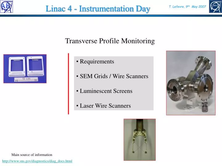
Linac 4 - Instrumentation Day. T. Lefevre, 9 th May 2007. Transverse Profile Monitoring. Requirements SEM Grids / Wire Scanners Luminescent Screens Laser Wire Scanners. Main source of information. http://www.sns.gov/diagnostics/diag_docs.html.

E N D
Linac 4 - Instrumentation Day T. Lefevre, 9th May 2007 Transverse Profile Monitoring • Requirements • SEM Grids / Wire Scanners • Luminescent Screens • Laser Wire Scanners Main source of information http://www.sns.gov/diagnostics/diag_docs.html
Transverse Profile Monitors : Requirements (1) SEM Grids in preparation Recuperate 3 Wire Scanners from LPI ‘SEM Grids’ ‘Wire Scanners’ ‘Screens’ ‘Laser Wire Scanners’ 25 Profile monitors 40mA 400ms 2Hz 80mA 400ms 2Hz
Transverse Profile Monitors : Requirements (2) • Spatial and temporal resolution should be easily achievable • Intense Beam (~1014 particles per pulse) • No problem for signal amplitude • Beam power and power density are high : Risk of Damage! • Mechanical design is strongly constraint by space limitation (Tbd = To be defined ; Tbc : To be confirmed)
SEM Grid / Wire Scanners (1) 100mm thick SiC wire Energy deposition in wire, max at about 270 MeV Protons pass through for energies over about 3.5 MeV Electrons stop until about 270 MeV Wire signal Depends on wire material and its thickness • SEM from H- • Electrons, protons stopping inside the material • SEM from Electrons and Protons leaving the wire Expected signal Calculations from M. Plum @SNS
SEM Grid / Wire Scanners (2) Choice of the wire must be done precisely
SEM Grid / Wire Scanners (3) Thermal limitations Cooling from Thermal conduction and black body emission Heating from the beam • Electron beam characteristics : • s : RMS beam size • Particle Flux : N(t) Pulse duration, repetition rate Target characteristics : e : Emissivity d : Thickness cp : Specific heat r : Density k : Thermal conductivity ss the Stefan-Boltzmann constant
SEM Grid / Wire Scanners (4) There are strong limitations to observe the full beam @low energies Reduce the pulse length DT for different materials and different beam energies
SEM Grid / Wire Scanners (5) Parameter to be considered in the optimization • The peak thermo-ionic current should be at least 100 times lower than the peak secondary electron emission current to avoid substantial contribution to the secondary electron signal. • Thermo-ionic emission proportional to the wire surface (diameter)
Luminescent screens Thermal limitations for Al2O3:Cr3+ screen Can be used at higher energies with reduced beam charge • No limitation from light intensity • 0.5mm Spatial resolution is easy • Provide more information than just profiles • No time resolution with thermal resistant Al2O3 • Space constraint to be checked • Thermal limitation
Laser Wire Scanner (1) • Based on • The detection of released electrons using a magnet and a collector • Measured the decrease of H- with a wall current monitor ‘By counting the number of the photoneutralization as a function of the laser position the bunch profile is reconstructed ‘ Photo-neutralization High power laser hn0 e- (b, g) Y=/2 Scanning system H- H H- beam
Laser Wire Scanner (2) y z x x y z • Efficient for small beam size • Need high power laser Laser Beam l0 : Laser wavelength tlaser : Laser pulse duration sw : RMS spot size ZR: Rayleigh range Particle Beam t : RMS Bunch length s : Transverse RMS beam size s sw ZR t tlaser l0 • The number of interactions is given by with A the interaction area, Np and Nlaser are the number of particles and photons in A
Laser Wire Scanner (3) Nd:YAG laser has l=1064 where the cross section is about 90% of the maximum. • First ionization potential for H- ions is 0.75eV. Photons with l<1500nm can remove an electron leaving neutral H plus electron • Photo-neutralization cross section is equal to s~ 4 10-21m2 Laser neutralization cross section *J.T. Broad and W.P. Reinhardt, Phys. Rev. A14 (6) (1976) 2159.
Laser Wire Scanner (4) Evolution with Beam energy
Laser Wire Scanner Versus Wire scanner Laser Wire • Non perturbative method • Time resolution possible • Limited to “small beam size” (~ 2mm) ? • Limited dynamic range : Possible of background (Stripping from residual gas, Beam losses) • External magnets are required • Higher Cost ? Conventional Wire • High risk of damage • Signal to noise not a problem • Maintenance requires vacuum access • Very radiation hard
Conclusions • Dynamic range and time resolution to be defined for each monitor • (design of the electronic) • Choice of detector is strongly constrained by: • Limited space available • Important thermal limitations for any intercepting devices (SEM/Wire/Screen) • Choice of the Wire to be studied • - Screens and Laser wire scanner present some advantages and should be investigated
Luminescent screens The number of Black body photons emitted per second in the wavelength range [la, lb] and in 2p sr is given by: k the Boltzmann constant, h the Planck constant, and c the speed of light.
LANL diagnostics deliverables 402.5 MHz 805 MHz HEBT MEBT To Ring and TGT DTL CCL SRF, ß=0.61, 0.81 RFQ Injector 1000 MeV 86.8 MeV 186 MeV 2.5 MeV MEBT 5 WS (elec. only) 6 BPM (elec. only) 2 Sl&Col (act. only) DTL 5 WS 10 BPM 6 CM (p/u only) 5 ED/FC D-plate (7.5 MeV) 1 WS 3 BPM 1 CM (p/u only) 1 ED/FC 2 Sl&Coll emit 1 Phosphor screen 1 8 seg. halo scraper 1 Beam stop / F-Cup CCL 8 WS 12 BPM 2 CM (p/u only) 1 ED/FC SCL 32 WS (16 elec.) 32 BPM HEBT 3 WS (dumps) 22 BPM (elec. only) RTBT 1 Harp Key WS = wire scanner BPM = beam position monitor Sl&Col = slit and collector emittance station CM = current monitor ED/FC = energy degrader & Faraday Cup
SNS Wire scanner signal levels Signals at center of beam, 26 mA avg. beam current • 32 micron dia. carbon wire. • Electronics should measure down to 1% of weakest signal from 5 mA avg. beam current, and up to about 200% of strongest signal from 26 mA avg. beam current • Total current range is 16 nA to 1.8 mA. *Transition from neg. to pos. signal at about 107 MeV. Note: Signal levels are accurate to about a factor of two. 32 micron C wire 380 MeV 0.12 cm x 0.12 cm rms beam
SNS Wire Temperature • 32 micron C wire. • Temperatures at center of beam. • Max temp is 1225 deg. C. • Requirements are met for all except MEBT (outside the scope of this review). 0 WS #5 1 1 Hz, 50 us, 26 mA beam 2 10 Hz, 3 106 MeV 4 200 MeV 5 1 Hz, 100 us, 26 mA 6 10 Hz, 100 us, 26 mA
SNS Laser Wire Scanner Single laser station 1) More resources available for a higher quality laser 2) Requires some sort of distribution system One laser per station 1) Simple 2) Quality of laser severely limited by the budget Choice: Single laser
SNS Laser Wire Scanner Q-switched laser 1) Less expensive 2) Not necessary to match the phase of the ion pulse train 3) Only 1% of the laser energy overlaps with the ion pulses Mode-locked laser 1) All of the optical energy available for neutralization 2) Because less energy per pulse is needed, optical damage is less likely 3) Longitudinal profiling also possible 4) More expensive 5) Pulses must be properly timed Choice: Q-switched laser
SNS Laser Wire Scanner Distribution by fiber 1) Optical damage likely, especially with longer, Q-switched pulses. 2) Radiation darkening would be a serious problem. 3) For mode-locked pulses, additional dispersion compensation would be required Distribution by direct beam propagation 1) Optical damage less likely 2) System should accommodate multiple laser systems 3) Active stabilization may be necessary Choice: Direct beam propagation
SNS Laser Wire Scanner Beamline optics in dry purge 1) Special stages and mounts not required 2) Purge should be sufficient to keep optics clean. Beamline optics in vacuum 1) Requires “vacuum-safe” optical stages and mirror mounts Choice: Dry purge
SNS Laser Wire Scanner • Sources of background are • Stripping on residual gas • 38mA; 200MeV; 1e-9 torr nitrogen; 1ms: 3.3e6 electrons/m • 10-3 background in 10cm detector • 20mA; 200MeV; 1e-9 torr nitrogen; 50us: 8.7e4 electrons/m • < 10-4 background in 10cm detector • Beam losses • 1W/m -> Ne = 2e6 for 10cm^2 collector area at 200MeV Ne = 4e5 for 10cm^2 collector area at 1000MeV • Can be major source of background (~1e-2) • Time gating can help • Experience from other machines? (PSR, etc.)