Download
1 / 80
910 likes | 1.17k Vues
11 – AC Motors. The intent of this presentation is to present enough information to provide the reader with a fundamental knowledge of AC Motors used within Michelin and to better understand basic system and equipment operations .

E N D
The intent of this presentation is to present enough information to provide the reader with a fundamental knowledge of AC Motors used within Michelin and to better understand basic system and equipment operations. By enrolling in this self-study course, you have demonstrated a desire to improve yourself and Michelin Manufacturing. However, this self-study course is only one part of the total Michelin training program. Practical experience, IMS (AP) school, selected reading, and your desire to succeed are also necessary to successfully round out a fully meaningful training program. Although the words “he,” “him,” and “his” are used sparingly in this course to enhance communication, they are not intended to be gender driven or to affront or discriminate against anyone.
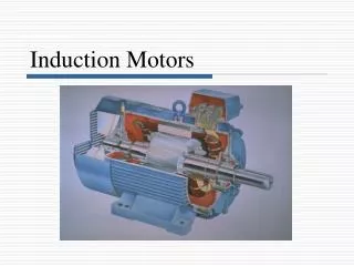
11 – AC Motors Three Phase AC Induction Motors There are two main types of induction motors: - Squirrel-Cage - Wound Rotor Both motors operate on induction and the principles are very similar. Let's first discuss the squirrel-cage motor and its construction since it is the simplest form. We will then look at the differences and applications of the wound rotor induction motor.
11 – AC Motors Squirrel-Cage Induction Motor Construction Stator- The stationary winding of the motor and it provides the rotating magnetic field. The stator windings are wound around the laminated pole pieces, which are mounted to the outside housing of the motor. It is also connected to the AC supply.
11 – AC Motors Squirrel-Cage Induction Motor Rotor - The rotating member of the motor and it provides the torque or power to do the mechanical work. The rotor is made of circular laminations with copper or aluminum bars imbedded around the outside edge. It is connected to the shaft of the motor.
11 – AC Motors Squirrel-Cage Induction Motor End Bells- Support the shaft of the motor and house the bearings.
11 – AC Motors Squirrel-Cage Induction Motor End Bells- Support the shaft of the motor and house the bearings.
11 – AC Motors The Wound Rotor Induction Motor This motor consists of three electrical parts: 1. A set of insulated windings mounted on the body of the motor. These windings are similar to those of the squirrel-cage induction motor and are also called the stator windings.
11 – AC Motors The Wound Rotor Induction Motor A set of insulated windings recessed into the laminated plates of the rotor. These windings are always connected in the wye configuration with the three free ends brought out and each one connected to each of three brass rings mounted on the motor shaft. These rings are the slip rings. A means of making electrical connection with the slip rings is needed so that current may flow through the rotor windings when they are in rotation. These connections are by means of brushes, which are held in position in contact with the slip rings by the brush-holder.
11 – AC Motors The Wound Rotor Induction Motor Construction The wound rotor is constructed of windings instead of shorting bars, as in the squirrel-cage induction motor. Like the squirrel-cage induction motor, it receives its power through induction. Its windings are connected in a star configuration, and are accessible through the use of slip rings and brush assembly. This access to the rotor circuit is the major advantage of the wound rotor induction motor. It allows changes in rotor impedance, through external resistance changes. This allows the torque of the motor to be controlled. The wound rotor induction motor can be used where the maximum torque is desired throughout the entire speed range. As the speed changes, rotor circuit resistance is varied to maintain the resistance of the rotor equal to the inductive reactance of the rotor (R = XL). When R and XL are equal, the phase angle of the impedance of the rotor is 45°.
11 – AC Motors The Wound Rotor Induction Motor The following basic block diagram illustrates the connection of external resistors to the rotor: The external resistance is usually of a value such that the resistance of the rotor circuit is equal to, or greater than, the rotor reactance at standstill. The wound-rotor motor is usually started with all the resistance in the rotor circuit. Starting torque with all the resistance is at maximum. As the motor comes up to speed, the rotor resistance is shorted out by a contactor. With all external rotor resistance cut out, the motor has good speed regulation, but somewhat less than that of the standard squirrel-cage motor. This can also be done in stages with numerous contactors as is illustrated on the following page.
11 – AC Motors The Wound Rotor Induction Motor
11 – AC Motors The Wound Rotor Induction Motor Operating Characteristics The insertion of resistance in the rotor circuit limits the starting surge of current and also permits high starting torque and adjustable speed. If all the resistance of the resistor banks is connected into the rotor circuit when the motor is running, the rotor current becomes less, and the motor slows down. As the rotor speed decreases, more voltage is induced in the rotor windings due to the stator rotating magnetic field speed being constant. As a result, more current flows in the rotor windings, which creates the necessary torque at the reduced speed.
11 – AC Motors The Wound Rotor Induction Motor Speed Regulation To increase the speed, for full speed operation, the rotor winding resistance is shorted out through the contactor. Although the insertion of resistance in the rotor circuit improves the starting torque at low speeds, it has the opposite effect at normal speeds. Thus the speed regulation of the motor is poorer with resistance in the rotor circuit. The resistance is shorted out as the motor comes up to speed in order to maintain running torque and better speed regulation. Although inserting the external resistance into the rotor circuit will vary the speed of the motor by changing the torque, this method is only seen in older installations.
11 – AC Motors The Wound Rotor Induction Motor Applications Because the wound rotor induction motor is similar to the squirrel-cage induction motor, it is used in similar applications. However, the wound rotor induction motor is seen more often in applications where some speed or torque control is needed. As discussed earlier, we can manipulate the torque of the wound rotor induction motor by changing the value of the externally connected resistances. Because torque has a direct affect on speed, we will also be varying the speed of the motor. Wound rotor motors can be used as variable-speed motors. Their initial cost is much greater, so they are usually used only where frequent large starting currents exist and for loads that require slow acceleration with controlled torque. Wound rotor motors are most frequently used in applications where high values of starting torque and low starting currents are required; also, where the inertia of the driven machine is extremely high.
11 – AC Motors Theory of Operation Rotating Magnetic Field The speed of the rotating magnetic field is called the synchronous speed of the motor. The following formula can be used to determine the speed of the rotating magnetic field created by the stator: Where Ns is the speed of the stator rotating magnetic field in RPMs f is the frequency of the applied voltage in hertz (Hz) P is the number of pair of poles per phase in the stator winding
11 – AC Motors Theory of Operation When motor manufacturers describe a 2-pole motor, they are talking about the numbers of poles that are created in the rotor due to the rotating magnetic field. For a 2-pole motor which has only 1 pair of poles per phase: Ns= 3600 rpm (assuming 60 Hz) For a 4-pole motor which has 2 pair of poles per phase: Ns= 1800 rpm (assuming 60 Hz) For a 6-pole motor which has 3 pair of poles per phase: Ns= 1200 rpm (assuming 60 Hz) For a 8-pole motor which has 4 pair of poles per phase: Ns= 900 rpm (assuming 60 Hz)
11 – AC Motors Theory of Operation As we saw in the generation of a three phase AC voltage, phase A is +VMax, phase B is -1/2 VMax, and phase C is -1/2 VMax. Also, notice that phase B will be +VMax next, then phase C. If we reversed the phasing for phase B and C, phase C would be next, then B. This is important in understanding how to reverse the rotation of a three phase motor. All you have to do is reverse any two phases. The illustration on the next page simulates the rotating magnetic field produced by the stator and its effect on the rotor. Notice where the voltages are assigned and, also, how the currents are flowing.
11 – AC Motors Theory of Operation The results of this analysis are shown for voltage points 1 through 7 in the figure below. At point 1, the magnetic field in coils 1-1A is maximum with polarities as shown. At the same time, negative voltages are being felt in the 2-2A and 3-3A windings. These create weaker magnetic fields, which tend to aid the 1-1A field. At point 2, maximum negative voltage is being felt in the 3-3A windings. This creates a strong magnetic field which, in turn, is aided by the weaker fields in 1-1A and 2-2A. As each point on the voltage graph is analyzed, it can be seen that the resultant magnetic field is rotating in a clockwise direction. When the three-phase voltage completes one full cycle (point 7), the magnetic field has rotated through 360º .
11 – AC Motors Relative motion of the conductor F Direction of the magnetic flux lines N to S B Induced current into the conductor I Theory of Operation In AC theory we learned the left-hand rule for conductors, the left-hand rule for coils, and the left-hand rule for generators. We now can use those rules to show how the rotating magnetic field is created in the stator. The following diagram can be used to illustrate the creation of the stator rotating magnetic field and explain why the rotor rotates. Notice the voltage at point A versus points B and C. These voltages and currents are happening at a given instant in time (A on the three phase sine wave). Also notice, that one conducting bar of the rotor is darker than the others. If we evaluate what happens when the rotating magnetic field is rotating clockwise (from A to B, then C), this rotation of the stator magnetic field causes the relative motion of the darkened conductor to be to the opposite direction. If the induced current is coming out of the board, as illustrated, then the flux lines cause the rotor to also rotate clockwise.
11 – AC Motors Theory of Operation Induction Motor Slip An induction motor cannot run at synchronous speed since the rotor would be standing still with respect to the rotating field and no current would be induced in the rotor. The rotor speed must be slightly less than synchronous speed in order that current be induced in the rotor to permit rotor rotation. The difference between rotor speed and synchronous speed is called slip: Where NS = synchronous speed, in rpm Nr= rotor speed, in rpm Slip can also be expressed as a percent of synchronous speed: Where NS = synchronous speed, in rpm Nr = rotor speed, in rpm
11 – AC Motors Theory of Operation Induction Motor Slip To calculate the actual shaft speed of an induction motor this relationship will be used: Where: Nr = is the actual shaft speed in RPMs f = is the frequency of the applied voltage in hertz (Hz) P = is the number of pair of poles per phase in the stator winding
11 – AC Motors Theory of Operation Induction Motor Efficiency The three-phase, squirrel-cage induction motor operates at a relatively constant speed from no-load to full-load. Because of the extremely low impedance of the rotor, only a slight decrease is speed is necessary to cause a large increase in rotor current to develop the necessary torque to turn the increased load. The percent slip at no-load is less than 1% while at full-load it is usually between 3-5%. This small change in percent slip from no-load to full-load likewise indicates why a squirrel-cage induction motor is considered a fairly constant speed motor. As the slip increases in a straight line characteristic, the rotor current will likewise increase in practically a direct proportion and cause the torque to increase as a straight line characteristic.
11 – AC Motors Theory of Operation Induction Motor Efficiency The losses in an induction motor consist of the stray power losses and the copper losses. The stray power losses include mechanical friction losses, windage losses, and iron losses. These remain relatively constant at all load points and are often called fixed losses. The second group of losses, called copper losses, is the I2R losses in the windings of the motor. As the current increases in the motor windings with an increase in load, the I2R losses increase. At light loads the percent efficiency () is low because the fixed losses become a smaller part of the input and the efficiency increases to its maximum value. However, when the rated capacity of the motor is exceeded, the copper losses become excessive and the efficiency decreases.
11 – AC Motors Theory of Operation Induction Motor Efficiency The efficiency of an AC induction motor can be determined by: Where = Greek letter eta, percent efficiency Pout = the output power produced by the shaft in watts Pin = the input power required in watts Example: Given: Pin = 8500 watts Pout = 10 hp Find: =
11 – AC Motors Nameplate Data NEMA Nameplate Data What Do All Those Things on an AC Motor Nameplate Mean? Introduction: What does all that extra information on the nameplate mean? To define the basic performance and mounting parameters of a motor, the National Electrical Manufacturers Association (NEMA) defines some basic design and dimensional parameters in NEMA Standard MG 1. These parameters are then coded onto the motor nameplate to give you a basic definition of what you have received. Manufacturers often include additional information to further define some key motor features.
11 – AC Motors * Manufacturer's type and frame designation * Horsepower output. * Time rating. * Maximum ambient temperature for which motor is designed. * Insulation system designation. * RPM at rated load. * Frequency. * Number of phases. * Rated load current. * Voltage. * Code letter for locked rotor kVA. * Design letter for medium motors. * NEMA nominal efficiency * Service factor if other than 1.0. * For motors equipped with thermal protectors, the words "thermally protected". . Nameplate Data NEMA Nameplate Data This standard section, "Nameplate Marking for Medium Single-Phase and Poly-phase Induction Motors," of the NEMA standard requires that "The following minimum amount of information shall be given on all nameplates of single-phase and poly-phase induction motors.“ * For motors rated above 1 HP equipped with over-temperature devices or systems, the words “OVER TEMPERATURE PROTECTED _____". A type number inserted in the blank would identify the protection type.
11 – AC Motors Nameplate Data NEMA Nameplate Data The information on a motor nameplate can be arranged in categories. By definition, an induction motor converts electrical energy to useful mechanical energy. With rated electrical input the motor will deliver rated output shaft power. There are established standard indicators of how effective the motor does its job, as well as data on the nameplate concerning safety and reliability. The following information provides a brief definition and some application considerations regarding motor data on the nameplate.
11 – AC Motors Nameplate Data Electrical Input Voltage The voltage at which the motor is designed to operate is an important parameter. One common misapplication is of motors (rated) at one voltage but applied on a different voltage using the + 10% voltage tolerance for "successful" operation. Nameplate-defined parameters for the motor such as power factor, efficiency, torque, and current are at rated voltage and frequency. Application at other than nameplate voltage will likely produce different performance. It is common for manufacturers to nameplate a wide variety of voltages on one motor nameplate. A common example is a motor wound for 230 and 460 V (230/460 V) but operable on 208 V. This 208-230/460V motor will have degraded performance at 208 V. Another common misconception is to request a motor rated at network voltage; for example, at 480 V. The NEMA standard is 460 V. The voltage rating assumes that there is voltage drop from the network to the motor terminals. Thus, the 460V motor is appropriate on a 480V network.
11 – AC Motors Nameplate Data Frequency Input frequency is usually 50 or 60 Hz. When more than one frequency is rated, other parameters that will differ at different input frequencies must be defined on the nameplate. The increasing use of adjustable frequency drives (AFDs) is also making it necessary to nameplate a frequency range, especially for hazardous-duty-listed applications. Phase This represents the number of ac power lines supplying the motor. Single and three-phase are the norms. Current Rated load current in amps is at nameplate horsepower (HP) with nameplate voltage and frequency. When using current measurement to determine motor load, it is important that correction be made for the operating power factor. Unbalanced phases, under-voltage conditions, or both, cause current to deviate from nameplate AMPS. Review both motor and drive for a matched system regarding current on AFD applications.
11 – AC Motors Nameplate Data Code A letter code defines the locked rotor kVA on a per-hp basis. Codes are defined by a series of letters from A to V. Generally, the farther the code letter from A, the higher the inrush current per hp. A replacement motor with a "higher" code may require different upstream electrical equipment, such as motor starters. Type The NEMA standard requires manufacturer's type, but there is no industry standard regarding what this is. Some manufacturers use "Type" to define the motor as single or polyphase, single or multispeed, or even by type of construction. Type is of little use in defining a motor for replacement purposes unless you also note the specific motor manufacturer.
11 – AC Motors Nameplate Data Power factor Also given on the nameplate as "P.F." or PF," power factor is the ratio of the real power (W) to the apparent power (VA) expressed as a percentage. It is numerically equal to the cosine of the phase angle. For an induction motor, power factor also varies with load. The nameplate provides the power factor for the motor at full load. Real power is the power that does work; apparent power has a reactive component. This reactive component is undesirable - the utility company must supply it, but it does no work. A power factor close to unity (100%) is most desirable. Because there are tradeoffs when designing an induction motor for improved efficiency or other performance parameters, power factor sometimes suffers. It can be improved by adding capacitors.
11 – AC Motors Mechanical Output Horsepower Shaft horsepower is a measure of the motor's mechanical output rating, its ability to deliver the torque required for the load at rated speed. It is usually given as "HP" on the nameplate. In general: HP = (Torque) x (speed)/5,250 where: Torque is in lbs.-ft. Speed is in rpm. Full-load speed The speed at which rated full-load torque is delivered at rated power output is full-load speed. It is generally given as "RPM" on the nameplate. This speed is sometimes called "slip" speed or actual rotor speed rather than synchronous speed. An induction motor's speed is always less than synchronous speed and it drops off as load increases. For example, for 1800 rpm synchronous speed, an induction motor might have a full-load speed of 1748 rpm.
11 – AC Motors Design The NEMA standard defines "design," which defines the torque and current characteristics of the motor. Letters are assigned the defined categories. Most motors are Design B, although the standard also defines Designs A, C, and D. Common headings on nameplates include "Des," "NEMA Design," and "Design." Some motors may not conform to any torque-current characteristics. The motor manufacturer may assign them a letter that is not a defined industry standard. It is important to check the design letter when replacing a motor in an existing application. Another note on Design B: Design B constrains the motor designer to limit inrush current to established standards. This insures that the user's motor-starting devices are suitable. A Design A motor has torque characteristics similar to those of the Design B motor, but there is no limit on starting inrush current. This may cause starter sizing problems. You should be aware of this and work with the motor manufacturer to insure successful operation of your motor systems.
11 – AC Motors Performance NEMA Nominal Efficiency Efficiency is defined as output power divided by input power expressed as a percentage: (Output Power / Input Power) x 100 NEMA nominal efficiency on a nameplate represents an average efficiency of a large population of like motors. The actual efficiency of the motor is guaranteed by the manufacturer to be within a tolerance band of this nominal efficiency. The band varies depending on the manufacturer. However, NEMA has established the maximum variation allowed. The maximum allowed by NEMA standards represents an additional 20% of motor losses from all sources, such as friction and windage losses, iron losses, and stray load losses. Therefore, you should pay attention to guaranteed minimum efficiencies when evaluating motor performance.
11 – AC Motors Service factor The service factor (S.F.) is required on a nameplate only if it is higher than 1.0. Industry standard service factor includes 1.15 for open-type motors and 1.0 for totally-enclosed-type motors. However, service factors of 1.25, 1.4, and higher exist. It is not considered good design practice to use the rating afforded by S.F. continuously; operating characteristics such as efficiency, power factor, and temperature rise will be affected adversely. Duty This block on the nameplate defines the length of time during which the motor can carry its nameplate rating safely. Most often, this is continuous ("CONT"). Some applications have only intermittent use and do not need motor full load continuously. Examples are crane, hoist, and valve actuator applications. The duty on such motors is usually expressed in minutes.
11 – AC Motors Safety Special markings Many motor nameplates have special markings to reflect third-party certification or recognition. Some common markings are: * CSA Indicates that the manufacturing system and the motor components meet the standards of, the Canadian Standards Association. UL indicates that the manufacturing system and the motor components meet the standards of, Underwriters Laboratories. Reliability Insulation class Often abbreviated "INSUL CLASS" on nameplates, it is an industry standard classification of the thermal tolerance of the motor winding. Insulation class is a letter designation such as "A," "B," or "F," depending on the winding's ability to survive a given operating temperature for a given life. Insulation classes of a letter deeper into the alphabet perform better. For example, class F insulation has a longer nominal life at a given operating temperature than class A, or for a given life it can survive higher temperatures. Operating temperature is a result of ambient conditions plus the energy lost in the form of heat (causing the temperature rise) as the motor converts electrical to mechanical energy.
11 – AC Motors Maximum ambient temperature The nameplate lists the maximum ambient temperature at which the motor can operate and still be within the tolerance of the insulation class at the maximum temperature rise. It is often called "AMB" on the nameplate and is usually given in degrees C. Altitude This indicates the maximum height above sea level at which the motor will remain within its design temperature rise, meeting all other nameplate data. If the motor operates below this altitude, it will run cooler. At higher altitudes, the motor would tend to run hotter because the thinner air cannot remove the heat so effectively, and the motor may have to be derated. Not every nameplate has an altitude rating.
11 – AC Motors Construction Enclosure This designation, often shown as "ENCL" on a nameplate, classifies the motor as to its degree of protection from its environment, and its method of cooling. NEMA describes many variations. The most common are Open Drip-Proof (ODP) and Totally Enclosed Fan Cooled (TEFC). ODP-An open drip-proof motor allows a free exchange of air from outside the motor to circulate around the winding while being unaffected by drops of liquid or particles that strike or enter the enclosure at any angle from 0 to 15 deg. downward from the vertical. TEFC-A totally enclosed fan cooled motor prevents free exchange of air between inside and outside the motor enclosure. It has a fan blowing air over the outside of the enclosure to aid in cooling. A TEFC motor is not considered air or water-tight; it allows outside air containing moisture and other contaminants to enter, but usually not enough to interfere with normal operation. If contamination is a problem in a given application, most manufacturers can provide additional protection such as mill & chemical duty features, special insulations and internal coating, or space heaters for motors subject to extended shutdown periods and wide temperature swings that could make the motor "breathe" contaminants.
11 – AC Motors Construction Frame This nameplate block can offer a lot of information if the motor is nearly standard. The frame size sets important mounting dimensions such as foot hole mounting pattern, shaft diameter, and shaft height. NEMA standards do not set some dimensions that can turn out to be important if the motor must fit into a confined space. These include maximums of overall height and length, and maximum conduit-box extensions. The data in the "Frame" block can be hard to interpret when special shafts or mounting configurations are used. Some examples of frame designation: 445T-This motor is a modern standard T-Frame motor. Critical mounting dimensions for all manufacturers are as defined in the NEMA Standard. 445TC This T-Frame motor has a standard NEMA-defined C-face. 445TD This T-Frame motor has a standard NEMA-defined D-flange. 445U The dimensions of a U -Frame motor are defined by NEMA standards prior to 1965. The U- Frame is the predecessor to the present T -Frame motor, and typically it has the equivalent horsepower capability of a T Frame motor that is two frame sizes smaller.
11 – AC Motors Construction Frame For example, the T -Frame equivalent of a 445U Frame motor for 100 hp at 1,800 rpm is a 405T motor for the same power and speed. The first two digits of the frame size divided by 4 defines the height of the shaft centerline from the bottom of the feet. Thus, the shaft height of a 445T motor is 44 / 4 = 11 in. The third digit in the frame size determines the distance between the foot holes nearest the shaft and the opposite drive-end foot holes. Many manufacturers drill multiple foot holes in motor bases to allow mounting in short or longer frame positions. For example, a 445T motor base may have mounting holes for 444T and 445T motors. If special dimension designations appear, be sure to contact the motor manufacturer for dimensional information for a replacement.
11 – AC Motors Construction Bearings Though NEMA does not require it, many manufacturers supply nameplate data on bearings, because they are the only true maintenance components in an AC motor. Such information is usually given for both the drive-end bearing and the bearing opposite the drive end. Nameplate designations vary from one manufacturer to another. For rolling-element bearings, the most common is the "AFBMA Number." That is the number that identifies the bearing by standards of the Anti-Friction Bearing Manufacturers Association.
11 – AC Motors Construction Other data A typical nameplate also includes the motor's brand name, "Serial No." or other identifying number unique to that motor. This allows the manufacturer to trace the motor back through manufacturing. The nameplate also includes the manufacturer's name, and its principal city and state and "Made in U.S.A." if U.S.-made. The nameplate is a treasury of important information about a motor. If you specify, buy, maintain, or replace motors, you should know how to read them. Note: This material is not intended to provide operational instructions. Appropriate manufacturer instruction manuals and precautions should be studied prior to installation, operation, or maintenance of equipment.
11 – AC Motors Construction Other data A typical nameplate also includes the motor's brand name, "Serial No." or other identifying number unique to that motor. This allows the manufacturer to trace the motor back through manufacturing. The nameplate also includes the manufacturer's name, and its principal city and state and "Made in U.S.A." if U.S.-made. The nameplate is a treasury of important information about a motor. If you specify, buy, maintain, or replace motors, you should know how to read them. Note: This material is not intended to provide operational instructions. Appropriate manufacturer instruction manuals and precautions should be studied prior to installation, operation, or maintenance of equipment.
11 – AC Motors IEC Nameplate Data Motor wiring = 3 phase. Design frequency = 50 Hz. Ratings according to IEC frame sizes = IEC 34-1 Production number. Power of motor = 15 kW. (Power on the shaft not electric power) Nominal speed = 1450 r/min. Insulation Class = Cl. F. Power factor = Cos F 0.90. (at 1450 r/min)
11 – AC Motors IEC Nameplate Data Type of motor = Cat. No. ….. IP ratings = IP 54. Weight of motor = ….. Kg. • Connection terminalStar (Y). = • Input voltage Y connection = 380 V. • Total current Y connection = 29 A. • Connection terminal = Delta (Δ). • Input voltage Δ connection = 220 V. • Total current Δ connection = 50 A. • If the supply line voltage is 380 VAC, then motor must be Star (Y) connection. • If the supply line voltage is 220 VAC, then motor must be Delta (Δ) connection
11 – AC Motors IEC Nameplate Data
11 – AC Motors Wiring Configurations U.S. Dual Voltage Motor Connections It is common for U.S. electric motor manufacturers to build motors for connection to many different voltage sources. Manufacturing motors for dual voltages, such as 480/240 volt, enables the same motor to be used in applications where the line voltages are different. These motors have the same characteristics on either voltage. The speed and horsepower remain the same if the motor is operated on either the higher or lower voltage.
11 – AC Motors Wiring Configurations U.S. Dual Voltage Motor Connections Dual-voltage connections are either wye-connected or delta-connected. Each phase is divided into two sections with the same number of coils in each section and nine external connections are brought out from these sections when the motor is wound. Each external lead or connection is stamped on the wire or at the terminal block with a number from one to nine.
11 – AC Motors Wiring Configurations Wye-Connected Motors Below illustrates the connections and terminal markings for a wye-connected, dual-voltage induction motor. In the series-wye connection illustrated on the left, the ascending numbers go in succession in a clockwise direction to the three points of the wye. Then starting at the end of the T1 winding, go around clockwise again, completing the three outside groups. The third start is on the inside wye just below T4, and go around clockwise again. This makes the nine external terminals of the six windings. The other three terminals of the internal wye are connected inside the motor for a nine lead motor.