Download
1 / 20
200 likes | 462 Vues
Beam Dynamics. Yunhai Cai June 7, 2006 DOE review. Professors: Alex Chao Ron Ruth Post doctor: Yuantao Ding Students: Boaz Nash Jerry Wang Administrative: Tom Knight Margie Bangali. Department head: Yunhai Cai Deputy: Gennady Stupakov Staff: Sam Heifets Karl Bane

E N D
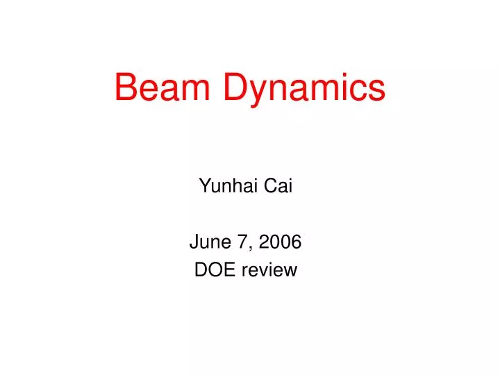
Beam Dynamics Yunhai Cai June 7, 2006 DOE review
Professors: Alex Chao Ron Ruth Post doctor: Yuantao Ding Students: Boaz Nash Jerry Wang Administrative: Tom Knight Margie Bangali Department head: Yunhai Cai Deputy: Gennady Stupakov Staff: Sam Heifets Karl Bane Zhirong Haung Yiton Yan Yuri Nosochkov Bob Warnock Martin Lee Members in Beam Physics Department
Activities in Beam Physics Department • Accelerator support: • Improve machine optics and study the beam-beam effects for PEP-II • Design lattices for ILC, SABER, and SPEAR3 • Estimate impedance and analyze and mitigate instabilities for ILC • Calculate wakefield and study CSR and FEL physics for LCLS • Accelerator research: • Develop precision methods to measure optics in circular accelerators • Develop tools to calculate luminosity and beam-beam lifetime in e+e- colliders • Phase-space manipulations of high-brightness electron beams • Study coherent synchrotron radiation and its dynamical effect on the beam • Advance theory and calculation of the impedance beyond conventional condition, such as rough surface, grooved surface • Study multi-particle beam dynamics; for example, interaction of beams with ions or electron cloud in accelerators • Various problems related to the advancement of Free-Electron Lasers • Theoretical analysis of laser acceleration in a vacuum • Community service: • Teach at Stanford University and at several particle accelerator schools • Serve on advisory committee for many accelerator complexes worldwide • Develop and maintain codes: LEGO, BBI, Zlib, MIA
Luminosity Increase as a Result of Improvement of Machine Optics • Lead the PEP-II optics task force and closely work with many colleagues in the Accelerator System Division • Significantly improve the online optics model for PEP-II • beam-based • faster and robust • Introduce many new correction schemes and tuning knobs • Better understanding of the machine nonlinearity • Improve chromatic optics • increase dynamic aperture
Precision modeling for PEP-II Using of Green’s functions and phase advances derived from beam orbits which are accurately measured with a Model-Independent Analysis (MIA) of BPM buffered data, we have been able to model the PEP-II linear optics reliably through SVD-enhanced Least-Square fitting of the quad components and sextupole feed-downs as well as BPM gains and cross couplings. PEP-II HER showed high-beta beat on Nov. 20, 2005, which were consequently corrected through modeling. PEP-II HER showed large Eigen coupling ellipse axis ratios (strong linear coupling) on Nov 20, 2005, which were subsequently corrected through MIA modeling.
PEP-II HER beta beat fix Through accurate modeling, we have been able to find and correct the magnet (QF5L) in PEP-II HER for fixing the high beta beat on March 16, 2006 PEP-II HER beta functions on March 16 after beta-beat correction.
PEP-2 LER Dynamic Aperture Simulation • Single beam dynamic aperture versus tune and Dp/p. • Realistic MIA machine model, b* = 36 / 0.8 cm. • Tune space near half-integer is limited by resonances, especially 2nx – nns , and chromatic tune spread. • Best aperture at tunes .522 < nx < .530, ny > .574. • Better compensation of the 2nd order chromatic ny tune shift is needed. ny nx 2nx-2ns 2nx-ns Dp/p 2nx-2ns best aperture nx+ny-4ns nx+ny-3ns > 10s aperture at Dp/p = 0 Dp/p = 5s = .00355
Beam-Beam Simulation and its Application to PEP-II previous working point • Three-dimensional simulation code: BBI • MIA models are used for the inputs • Simulation is carried out at currents of 1600mA/2400mA • Lower both x and y tunes to gain luminosity shown on a contour plot in unit of 1E33 cm-2s-1 We made a quantitative prediction and followed by: • MD study and identified beam-beam lifetime as the limitation • Run x-chromaticity -1 to improve chromatic optics • Tweaked SCY3 by 7% to gain beam-beam lifetime • Lower the VRF from 4.5 to 4.0 MV • Actual tune change was accomplished by operators during the delivery Y tune current working point X tune
Enhancement of resistive wall wake in finned beam pipe Geometry of finned chamber (a), and for problem that is actually solved (b). Magnetic field in the vicinity of a rectangular (a) and round (b) fin. Finned beam pipe has been proposed for the ILC damping ring to reduce secondary emission and thus the electron cloud effect Fins will increase the surface magnetic field induced by a bunch, and thus the resistive wall (rw) wake We calculate the enhancement, , of the rw wake using (a) Schwartz-Christoffel transformation and (b) A numerical solution of the Laplace equation We find that, for the proposed pipe, ~ 1.5 For round fin: enhancement factor as function of fin thickness over period, t/p.
Resistive wall wake in ILC delivery line [m] function for last 1600 m of ILC delivery line beam pipe radius, a [m], vs z [m] In the ILC delivery line, injection jitter or drift, or misaligned beam pipes will cause emit- tance growth due to the resistance of pipes For stainless steel: 1y’ injection drift => 80% emittance growth, 100 m rms beam pipe misalignment => 40% emittance growth Can relax tolerances by factor of 7 by going to copper or aluminum Have included also wakes of transitions relative emittance growth due to initial offset y’= y’ assuming stainless steel beam pipe
dump dump 20 mrad IR 2 mrad IR IP IP dump dump e+/- energy spread IP dump 20 mrad optics 2nd focus Design of ILC Extraction Optics for 20 and 2 mrad IRs 2 mrad extracted beam in QF1 coil pocket • Challenges: • needed small loss (~kW) for high power 11-18 MW e+/- and g beams • large energy bandpass for 50-80% energy spread and strong optics • small magnet separation near IP • 2 mrad beam is offset in the shared FF magnets and goes through non-linear field in the QF1 coil pocket. • Design: • < 1 kW electron loss on magnets for ILC nominal parameters • 50-60% energy bandpass through the magnets • diagnostic optics with the 2nd low-b focus for energy and polarization measurements. 2 mrad beam near IP
Design of SABER Optics bypass FF X b*=1/10 cm LCLS linac IP SABER bypass Y sx=5.1 mm sz=26 mm • Desired IP beam: E=30 GeV, N=2 1010, sx,y<10 mm, sz< 30 mm, h=h’=0. • New bypass optics for independent operation with LCLS, low beta final focus, existing South arc optics. • Compensation of 2nd order dispersion and chromatic beta with sextupoles. • Optimized bunch length compression. • Achieved (w/o magnet errors): sx=5.1 mm, sy=5.3 mm, sz= 26 mm, b*=1/10 cm for ge=50/5 mm. at IP sy=5.3 mm Dp/p z (mm)
Microwave Instability in Ultra-Low Momentum Compaction Lattice • Study of the beam dynamics for ultra-short bunches • Applicable to super B-factory or next generation of synchrotron radiation facilities • Found that the threshold of microwave instability is lower for the negative momentum compaction factor
Longitudinal Head-Tail Instabilitiesin a nearly Isochronous Lattice • Bunch length less than a millimeter in storage ring • Negative momentum compaction factor of -5.3E-4 with its nonlinear parts • Found that the head-tail instability in the longitudinal plane is a limiting factor as shown: The beam is splitting into two parts within 1000 turns • Feedback is not so effective to control this instability • Published in PRST, April 2006.
Simulation of Coherent Synchrotron Radiation (BC1) Entrance of BC1 Exit of BC1 CSR only Advance beam density through BC1
Calculation of beam impedance for long tapers and short bunches A general trend in modern accelerators is to use short bunches (20 micron rms bunch length in LCLS, 300 micron in ILC). Existing analytical methods of calculation of the high-frequency impedance cannot be easily generalized to other geometries. We developed a method of a parabolic equation for calculation of the high frequency impedance which effectively uses small parameters (such as the wavelength) of the system. The field calculated with the parabolic equation for a smooth, long-thin collimator, and the resulting impedance as a function of the length of the collimator.
Calculation of the beam field in the LCLS Bunch Length Monitor Maintaining a stable bunch length and peak current is a critical step for the reliable operation of a SASE based x-ray source. In the LCLS, a bunch length monitor (BLM) right after the bunch compressors is proposed based on the coherent radiation generated by the short electron bunch. The standard far field synchrotron radiation formula and well-developed numerical codes do not apply to the analysis of the BLM performance. We carried out a calculation which takes into account the near field effect, the effect of a short bending magnet, and the diffraction effect of the radiation transport optics.
X-ray Regenerative Amplifier FEL • SASE FELs are transversely coherent but temporally chaotic • We propose to use narrow-bandwidth crystals to filter and feed back x-rays for repetitive interactions with a bunch train Z. Huang & R. Ruth, PRL96, 144801 (2006) • May be implemented in LCLS with SLAC linac (using ~10 bunches in a 3-msec uncompressed rf pulse) • A fully coherent x-ray laser with two to three orders better spectral brightness than a SASE x-ray source
Effective gain enhancement Shorter saturation length Possibility to reach 1 Å saturation in LCLS undulator Energy spread effects are important Not sensitive to OK phase matching in SASE mode Undulator Undulator Undulator Undulator Undulator 4-dipole chicane for OK Optical Klystron (OK) Enhancement to SASE FELS λ= δE/E=1e-5 δE/E=5e-5 SASE 4 OK chicanes (in long undulator breaks) Y. Ding, P. Emma, Z. Huang, V. Kumar, submitted to PRST-AB (2006)
Conclusion • Recently, we have significantly improved the machine optics for PEP-II. The improvement gained us approximately 9% in peak luminosity with potential to gain an additional 10% as the beam currents increase to their previous values. • This improvement is a result of many research projects started more than five years ago. This demonstrated that long-term accelerator research could be critical to the success of accelerator operation. • We continue to make contributions to the other accelerator projects: ILC, SABER, and LCLS. • We continue to make progress in accelerator research in the areas of ultra-short bunches, coherent synchrotron radiation, and the physics of FEL.