Download
1 / 45
570 likes | 1.28k Vues
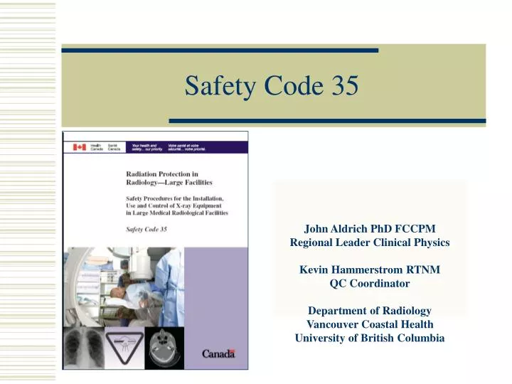
Safety Code 35. John Aldrich PhD FCCPM Regional Leader Clinical Physics Kevin Hammerstrom RTNM QC Coordinator Department of Radiology Vancouver Coastal Health University of British Columbia. Safety Code 20A (1976)

E N D
Safety Code 35 John Aldrich PhD FCCPM Regional Leader Clinical Physics Kevin Hammerstrom RTNM QC Coordinator Department of Radiology Vancouver Coastal Health University of British Columbia
Safety Code 20A (1976) Recommended safety procedures for the installation, use and control of x-ray equipment. Mainly concerned with the x-ray output parameters of the equipment Only film processor QC defined Safety Code 35 (2008) (two drafts in 2005 and 2007) Comprehensive safety procedures for the installation, use and control of x-ray equipment. Includes all x-ray systems Increased emphasis on patient dose 25% of the Code is concerned with QC of digital imaging systems Medical X-ray Safety Codes
Safety Code 35 A1. Responsibilities of owners and users (4) A2. Procedures for minimizing staff dose (2) A3. Procedures for minimizing patient dose (6) B1. Facility shielding (3) B 2-6. Equipment performance (15) C 1-3. Quality Control (17) Appendices (30)
Decoding the Code Normal Font – Required Test (“must do”) Italics - Recommended Test(“recommended”) Required Tests currently recommended by RPS • Handout includes all slides in our presentations • Attached sheets have all the tables enlarged • References are to details of the tests in the Code eg D1 is the first daily test listed, W1 – weekly, M1 - monthly, Q1 – quarterly, SY1 – semi-annually, Y1 - Annual
Daily Quality Control Tests Normal Font – Required Test (“must do”) Italics - Recommended Test(“recommended”) Required Tests currently recommended by RPS
Weekly and Monthly Tests Normal Font – Required Test (“must do”) Italics - Recommended Test(“recommended”) Required Tests currently recommended by RPS
Quarterly and Annual Tests Normal Font – Required Test (“must do”) Italics - Recommended Test(“recommended”) Required Tests currently recommended by RPS
Display QC • Daily (D7) – for clinical interpretation • Radiologist at each login • Find suitable SMPTE test pattern • Make accessible on PACS • Test using various user logins/profiles • Alert radiologists of requirement, frequency, and procedure
Problems with inconsistency Right Display – 5% not visible / 95 % visible Left Display – 5% visible / 95 % not visible • Should see both 5% and 95% squares if calibrated properly
Display QC • Monthly (M6) • All displays • Technologist • PACS administrator • Biomed • SMPTE test pattern / test pattern generator / vendor
Display QC • Annually (Y27) • Clinical interpretation and interventional use • QC Coordinator • PACS administrator • Biomed • SMPTE test pattern / test pattern generator / vendor QC software and photometer
Viewbox QC • Weekly visual inspection (W2) • Cleanliness • Viewing area discolouration • Improper luminance • Clean, replace plastic or bulb if necessary • Technologists / Biomed / Plant services
Viewbox QC • Yearly inspection (Y26) • Technologist / physicist • Maintain logsheet
Laser Film Printer QC • Weekly (W3) • Use same viewbox panel • Print SMPTE from PACS workstation or from printer menu • View 5% and 95% grayscale squares • Maintain logsheet
Laser Film Printer QC • Monthly (M7) • Use same viewbox panel • Print SMPTE from PACS workstation or from printer menu • Measure optical density of grayscale gradient squares, geometrical distortions, artifacts • View 5% and 95% squares and compare densitometer readings • Maintain logsheet
Radiation Protection • Radiation Safety Officer (1.4) • Room Shielding (5.0) • Lead aprons (4.1)
Radiation Safety Officer • There must be a Medical Physicist or Radiation Safety Officer to advise on all aspects of Radiation Safety • Planning, registration, inspection • Working conditions, procedures • Classification of personnel, dosimetry • Record keeping, investigations
Design of Shielding Recommend NCRP 147 (2004) methods which are based on empirical data (although Appendix is NCRP 49 (1976) which will tend to overshield rooms) Surveys of rooms must be done for new or altered rooms (equipment, use or vicinity Sec A5) Design shielding Check lead installation Measure radiation in surrounding areas Radiation Protection - Shielding
Lead Aprons Lead equivalence of aprons • SC 20A • <150 kVp 0.5 mm • SC 35 • < 100 kVp: 0.25 mm • 100< kVp <150: 0.35 mm • >150 kVp: 0.5 mm
Lead apron QC • Annually (Y28) • Radiographic / radioscopic • Rejection if total defective area > 670 mm2 • Thyroid and reproductive areas < 5 mm diameter equivalent total
Acceptance testing Baseline value determination Device use period Next constancy testing Data evaluation Within the established criteria PASS FAIL Remedy Equipment Life Cycle • Acceptance testing • New equipment • Conformance to manufacturer’s specifications/RFP • Baseline performance • Routine performance evaluations • Specific tests performed at regular intervals • Consistency checks • Evaluate malfunctioning or out-of-spec equipment
Test tool/phantom • Standard imaging parameters/conditions • Scheduled testing (Daily/Weekly) • Defined and objective acceptance/rejection criteria • Patient replaces the phantom • Non-standard imaging parameters/conditions • Frequent testing (every patient) • Ill-defined and subjective acceptance/rejection criteria Imaging QC Principles Proactive QCrather thanReactive QC • System performance rated BEFOREclinical imaging • System performance rated AFTER clinical imaging. Which approach would you prefer if you were a patient??
Radiographic Systems • Projection radiography • Film • Digital detectors (DR) • Computed radiography (CR)
Weekly Radiographic Tests Normal Font – Required Test (“must do”) Italics - Recommended Test(“recommended”) Required Tests currently recommended by RPS
Monthly Radiographic Tests Normal Font – Required Test (“must do”) Italics - Recommended Test(“recommended”) Required Tests currently recommended by RPS
Annual Radiographic Tests (1) Normal Font – Required Test (“must do”) Italics - Recommended Test(“recommended”) Required Tests currently recommended by RPS
Annual Radiographic Tests (2) Normal Font – Required Test (“must do”) Italics - Recommended Test(“recommended”) Required Tests currently recommended by RPS
Digital Imaging Any sufficiently advanced technology is indistinguishable from magic… Arthur C Clarke 1961
Digital X-ray Systems • Direct Radiography DR • Formation of image without a secondary read-out device • Computed Radiography CR • Use of storage phosphor plate usually in a cassette-based system
Digital System QC Film Developed And Fixed Viewed Display Detector Reading Digital Processing Stored PACS QC of the digital systems is an additional requirement – in addition to the usual x-ray performance tests - it is not performed magically
DR, CR and DF – Extra QC • Dose Calibration • Spatial Resolution • Low Contrast • Uniformity • Artifacts
Dose Calibration • Each system should be calibrated according to the manufacturers protocol, as they are all slightly different • General set-up • Arrange for defined dose at surface of cassette at 80 kVp • Expose and read image • Record Exposure Index • The image can also be used to check for uniformity, linearity and artifacts
Image Quality • All CR and some DR/DF manufacturers have custom Image Quality phantoms and automatic software to analyze image quality
Resolution and Contrast • Any high contrast resolution phantom can be used to provide comparative information • Low contrast resolution is one of the most difficult parameters to measure. There are several phantoms and measurement is subjective, so consistent technique is essential • Image Noise is usually be a good indicator of consistency
Digital Radiography QC • Many DR systems require more frequent calibration of the uniformity eg every month • Flat field measurement (uniform Cu orAl plate) • Uniformity correction • Noise • Artifacts • Contrast-detail and resolution phantom
CR & DR QC • Weekly visual inspection (W1) • Dust / dirt • Clean if necessary • Technologist • Monthly inspection / cleaning (M1) • Dust / dirt / damage • Clean each IP. Replace damaged IPs. • Technologist • Maintain logsheet