Download
1 / 31
380 likes | 1.12k Vues
Stray light computations: Has nothing changed since the 1970’s?. Alan Greynolds RAI Chief Scientist awgreynolds@earthlink.net August 2007. Presentation contents. 4 basic parts Review of stray light and analysis methods Historical review Current state-of-affairs

E N D
Stray light computations: Has nothing changed since the 1970’s? Alan Greynolds RAI Chief Scientist awgreynolds@earthlink.net August 2007
Presentation contents • 4 basic parts • Review of stray light and analysis methods • Historical review • Current state-of-affairs • Description of a new software tool • Sorry to disappoint but NO EQUATIONS!!
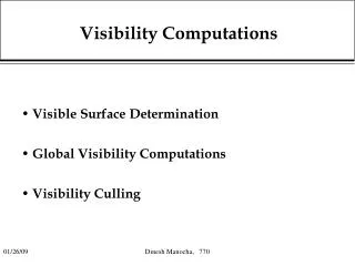
Review: Stray light mechanisms • Optical surfaces • Micro-roughness scattering (Angstroms RMS) • Particulate contamination scattering (cleanliness level) • If refractive • Ghost images (AR coatings) • Bulk scatter, however negligible for all but a few glasses like ZnS • Subsurface grinding/machining damage must be polished out • Mechanical structure • Roughness and coating reflectivity (paint, anodize, threaded, etc.) • For LWIR • Thermal emission (temperatures and emissivities) • Wide-angle diffraction from apertures
Minimum requirements of any stray light method/code • Model mechanical structure as well as optical surfaces • If ray based, non-sequential tracing • Means to specify angular/wavelength dependent coating/scatter properties of all surfaces • Large dynamic range (many orders of magnitude) • Finish computations in a reasonable amount of time (hours or days but not weeks or months)
Categorizing the different methods • Stochastic: Random estimation • or Deterministic: No randomness (accuracy independent of dynamic range) • Guided: Paths (at least partially) must be specified ahead of time • or Unguided: Paths found automatically (minimizes human input and thus errors) • Beam sub-division: Rays or pencils/beamlets • or Surface sub-division: Finite element mesh
Stochastic, beam sub-division, methods • Straight Monte-Carlo • All rays have same flux • What a ray does at each interaction determined by probabilities of each process • Physical results indicated by density of rays • Unguided and closest to reality: ray photon • Modified Monte-Carlo adds: • Ray splitting so must track flux of each (ghosting now deterministic) • Importance sampling directs scattered rays to areas of interest, i.e. guided
Stray light codes in the 1970’s • 1972 GUERAP-I (Chou, Honeywell FL) • Straight Monte-Carlo (1st non-sequential ray-tracer?) • 1973 GUERAP-II (Boyce et al, Perkin-Elmer CT) • Deterministic, known for sophisticated multiple diffraction • 1974 APART (Breault, Univ. of Arizona) • 3 subprograms (geometry => view factors => final computations) • Finite-element radiative transfer (paraxial imaging) • 1976 GUERAP-III (Likeness et al, Honeywell FL) • Modified Monte-Carlo (ray splitting, importance sampling) • 1979 APART1 (Greynolds, Univ. of Arizona) • “Quick and dirty” calculation embedded in 1st subprogram • Deterministic using 2D “bi-directional” imaging • Finds ALL single scatter paths but only for axial symmetry
Breakdown * Only surface sub-division one
Today’s commercial codes all based on GUERAP-III technique • ASAP (Breault Research, AZ) • OptiCAD (OptiCAD Corp, NM) • TracePro (Lambda Research, MA) • LightTools (Optical Research Associates, CA) • ZEMAX (ZEMAX Development, WA) • FRED (Photon Engineering, AZ) • and probably more
Why did GUERAP-III’s modified Monte-Carlo method win out? • Poor implementation of deterministic codes • Severe geometry restrictions (e.g. no CAD import) • Much too prone to human error • Monte-Carlo methods flexible and easy to implement once non-sequential ray-tracing implemented • Modified method eliminates wildly unrealistic computational times of straight Monte-Carlo
Today’s commercial codes differ only in implementation details • GUI and/or CAD and/or Scripting interface • Number, sophistication, and quality of scatter models • Sophistication of importance sampling and handling of overlapping ones (which would lead to non-conservation of energy) • Diagnostic outputs (what’s causing my stray light?) • Multi-core/processor support
Why no new deterministic or unguided codes today? • Harder to implement, especially for multiple levels of scatter • Unguided straight Monte-Carlo still too much even for today’s workstations (tomorrow’s?) • Modified Monte-Carlo essentially becomes deterministic in limit of a large enough number of small enough importance areas • Stray light is a VERY small niche market and all of today’s codes are more general purpose and have bigger fish to fry (e.g. lucrative automotive lighting market)
Sidebar: optical design parallel • The vast majority of imaging optics are still designed today using 1960’s Damped Least Squares method (or some variant of it) • A “guided” method in the sense it is a local optimizer, success depends heavily on user’s starting design and “tweaking” • However, hasn’t stopped vendors from also incorporating “unguided” global optimizers such as the stochastic Simulated Annealing method
Is it time to look for a better stray light method? • Revisit 1979, unguided, deterministic, beam sub-division, APART1 technique: • “can analyze all single scattering paths … both look into the system from the point source to determine the illuminated areas and look out from the detector to determine the final scattering areas. These areas are then matched up to determine if they overlap. If they do, the relative amount of energy scattered to the detector is calculated.” Overlap segment From one detector point From one out-of-field source
GelOE: a new more general implementation • Pronounced like the dessert • Based on a new fundamental element of geometry called a “gel” that bridges the gap between optical and CAD representations • OE stood for Optical Engineering (or Evaluation or whatever) • Prioritized development goals (relative to stray light capability of other codes) • Simpler and more practical • Better graphics and other outputs • More powerful in some areas, nearly as powerful in others • Portable to a variety of compilers/platforms (not just Microsoft) • Faster than most (transparent multiple core/processor support) • Internal proprietary tool, no plans to commercialize • Developed in spare time to support real-world engineering tasks
Main stray light enhancements • Easily handle arbitrarily complex geometries (e.g. automatically merge optics imported directly from multiple ZEMAX, CodeV, and/or ASAP models with detailed mechanics from full CAD model) • Instead of paraxial imaging, use bi-directional (into system and back from focal plane) real ray (actually beamlet) non-sequential tracing • Automatically calculate ALL ghosting, single level scattering, internal thermal emission, and any combinations thereof • Scatter not from crude 2D imaged line segment overlap but more accurate 3D differential beamlet overlap • Scatter and/or thermal characteristics can be changed without retracing geometry allowing quick “what if” studies
Generalizing to 3D (cutaway view) Overlap area
Calculating overlap of 2 finite beamlets incident on a surface • 1st beamlet from one of the sources, 2nd from one of the detector array points • With general anamorphic profiles, exact overlap difficult and time-consuming to do • Two simple approximations permit using two different closed-form convolution formulas • Remember this is stray light where dynamic range and speed is more important than precision • Overlap area combined with directional BSDF calculated at centroid of overlap leads to a precise increment of scattered irradiance at the detector point • Diffraction if aperture edge passes through overlap area
ASAP and GelOE scripts TITLE =Original Cassegrain example from thesis UNITS M WAVELENGTH 10 UM MEDIA; (N=2.4) =ZnSe MODELS LAMBERTIAN .0001 LAMBERTIAN .01 LAMBERTIAN .0001*N^2 EDGES RECTANGLE Z -5 2@.001 !primary image RECTANGLE Z .5 2@.004 !final image ENT OBJECTS OPTICAL Z -4.05 ELLIP 1.04 =Window; INTERFACE 0 1 0 "ZnSe" SCATTER MODEL 3; TOWARDS Z 1 (.001/5)/N OPTICAL Z -3.95 ELLIP 1.04 =Window.2; INTERFACE 0 1 "ZnSe" 0 SCATTER MODEL 1; TOWARDS Z 1 (.001/5) OPTICAL Z 0 -10 -1.0353 ELLIP 2@1 .31914 =Primary Mirror INTERFACE 1 SCATTER MODEL 1; TOWARDS 1 OPTICAL Z -3.9 -2.9333 -3.1576 ELLIP .24044 =Secondary Mirror INTERFACE 1 SCATTER MODEL 1; TOWARDS 2 PLANE Z .5 ELLIP .1 =Image TUBE Z -5 2@1.05 -.05 2@1 =Main Baffle Tube SCATTER MODEL 2; TOWARDS 1 TUBE Z -3.9098 2@.24044 -3.4231 2@.33623 =InnerSecondaryBaffle SCATTER MODEL 2; TOWARDS 1; TOWARDS 2 TUBE Z -2.0214 2@.18019 -.0051 2@.31914 =Outer Conical Baffle SCATTER MODEL 2; TOWARDS 1 TUBE Z -2.0214 2@.18019 .5 2@.1 =Inner Conical Baffle SCATTER MODEL 2; TOWARDS 2; TOWARDS 1 RETURN PROFILE BEAMS INC GEO; HALT 1.E-19 M=10000 $ITER ANGLE 1 29 -29 PSNIT { GRID ELLIP Z -5 -4@1.05 2@SQRT(4*M/3.1416) SOURCE DIR Z (ANGLE) 90; FLUX 0 COS[ANGLE] TRACE CONSIDER ONLY IMAGE; SELECT ONLY SOURCE -1; PATHS SPOTS POS ATT 0 YX PIXEL 1; DISPLAY; $GRAB 'Maximum' PSNIT CONSIDER ALL } : Additional importance sampling setup in bold TITLE =Original Cassegrain example from thesis, #2 beamlets UNITS M WAVELENGTH 10 UM MEDIA; 2.4 =ZnSe MODELS HARVEY .0001/PI 0 LAMBERTIAN .01 VANES Z 90 .2 .1 ENT OBJECTS SINGLET Z -4.05 .1 1.04 "ZnSe" =Window OPTICAL Z 0 -10 -1.0353 ELLIP 2@1 .31914 =Primary Mirror INTERFACE 1 OPTICAL Z -3.9 -2.9333 -3.1576 ELLIP .24044 =Secondary Mirror INTERFACE 1 TUBE Z -5 2@1.05 -.05 2@1 =Main Baffle Tube TUBE Z -3.9098 2@.24044 -3.4231 2@.33623 =Inner Secondary Baffle TUBE Z -2.0214 2@.18019 -.0051 2@.31914 =Outer Conical Baffle TUBE Z -2.0214 2@.18019 .5 2@.1 =Inner Conical Baffle RETURN BEAMS INC GEO BUNDLE LIF(#1==0,#2,0) GRID -Z .5 CIRC DIR SQRT(1/2) .18/2.52 BUN LIF(#1==0,2*#2,0) GRID -Z .5 CIRC DIR .18/2.52 BUNDLE LIF(#1>>0,#2,0) GRID Z -5 ELLIP POS 1.05 1.05*COS[#1] ROTATE X -(#1) 0 -5 END
GelOE’s graphical breakdown of major contributors (% by coating and object)
Is it possible to efficiently do unguided higher level scatter? • Haven’t found a fool-proof method, i.e. one that doesn’t take forever or miss important paths • Exception: treat multiple scatter within cavities of vane structures or threads as a single effective BRDF (Breault) • If not used properly, can under or over estimate scatter by an order-of-magnitude for some cases • However, one fast and simple scheme involves doing direct transfers from areas illuminated by sources to ones seen by detectors (that don’t overlap) • Similar to “radiosity” rendering method used in computer graphics • Combination of beam and surface sub-division • Seems to find a lot of the significant level 2 paths but obviously not all under all conditions
Trivial example of a Newtonian telescope with a re-imager Mirror scatter Baffle scatter → Mirror scatter Vane diffraction → Mirror scatter
So why bother to develop a new stray light tool? • GelOE really shines when applied to complex systems where setting up and testing the importance sampling could take days or weeks, e.g. • CAD models that result in 10s of thousands of surfaces • Dozens of optical components (reflective AND refractive AND diffractive) • Multiple FOVs (moving zoom components, both continuous and discrete) • Multiple wavelength channels (dichroic beamsplitters) • In last 3 years, has already been used to analyze and/or design dozens of real systems including …
Representative results, log(relative) and log(absolute) Internal thermal emission Solid lines are values at center of FP while “error bars” show min-max variation across FP Ghost
Closing remarks • Industry standard optical design/analysis methods are fine, but we shouldn’t stop looking for new (or revisiting past) innovative techniques • This is especially important because of the ever increasing power of our computer systems • The impractical can suddenly become practical • A far more important optical example than stray light: Yee’s 1966 FDTD solution to Maxwell’s equations has only recently come into widespread use for “real” 3D short wavelength problems
References • “GUERAP: General Unwanted Energy Rejection Analysis Program user's manual”,T.S. Chou, Honeywell Aerospace Div., St. Petersburg FL, Oct. 1972. • “GUERAP II - user's guide”,B. Boyce, B. Harris, R. Noll, Perkin-Elmer Corp., Norwalk CT, Feb. 1974. • “User's manual for University of Arizona APART program (Analysis Program - Arizona Radiation Trace)”, R.P. Breault, Tucson AZ, Aug. 1975. • “GUERAP III simulation of stray light phenomena”, S.S. Steadman, B.K. Likeness, Honeywell Avionics Div., St. Petersburg FL, Proc. SPIE, Vol. 107, Apr. 1977. • “Computer-assisted design of well-baffled axially symmetric optical systems”, A.W. Greynolds, Proc. SPIE, Vol. 193, Aug. 1979.; also University of Arizona M.S. thesis, 1980.
Commercial links • http://www.breault.com/resources/kbasePDF/bropn1157_straylight.pdf • http://www.opticad.com/features.html • http://www.lambdares.com/data/Tappnotes/straylight.pdf • http://www.opticalres.com/white%20papers/ScatterGlossy.pdf • http://www.zemax.com/index.php?option=com_content&task=category§ionid=5&id=44&Itemid=105 • http://www.photonengr.com/fred/straylght.html