Download
1 / 23
240 likes | 283 Vues
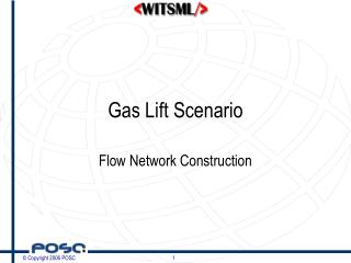
Automating Flow Control on Gas Lift Wells. Comparison of Alternative Methods. South American Production Facility. Conventional Automation. Electric Actuated Choke Valve Orifice Plate Flow Measurement Flow Computer. Conventional System Schematic. Flow Meter. Well Optimization Curve.

E N D
Automating Flow Control on Gas Lift Wells Comparison of Alternative Methods
Conventional Automation • Electric Actuated Choke Valve • Orifice Plate Flow Measurement • Flow Computer
System Problems • At lower injection rates (below 2.5 MMSCFD) the well produced intermittent flow
Advantages Simple Installation Uses Existing Hardware Inexpensive No Gas Emitted Operates at Last Set Point on Loss of Power Disadvantages Requires Piping Modifications Slow Actuator Speed of Response Deviations from Set Point Actuator Moves in Discrete Increments (2% typical) Very Small Movements Not Possible Conventional System Characteristics
Fail in Place Lockup SystemActivates on loss of power or gas supply pressure
Advantages Simple Installation No Piping Modifications No Deviation from Set Point Fast Speed of Response PID loop runs 16 times/sec Actuator can move in small increments (.1% typical) Simple System Integration Operates at Last Set Point on Loss of Power Disadvantages Requires Regulated Gas for Supply Gas Emitted StarPac Characteristics
Results • Crude Production Increase = 4.3% • Gas Usage Reduction = 3.3% • System Payback = 12 days • Potential Gas Reduction = 24% • (Change avg. rate from 2.9 to 2.2)
Why the Improvement? • Speed of Response & Repeatability • StarPac holds closer to flow set point when system instabilities occur • Changing gas supply pressure • Changing flow line or tubing pressure • Stability becomes more critical as flow rate decreases • System is more likely to get upset/unstable at minimal flow rates • Smaller deviations can cause instability