Download
1 / 9
90 likes | 279 Vues
Digital Electronic. Remote Control For Home Applications. www.Engg-Know.com. Remote Control For Home Applications. www.Engg-Know.com. Components: ( IC ( CD4017 5 volt ) Relay ( Diode( 1N4007 ) Five Resistors( 47 , 220K , 330 , 330 , 1K ) Ω Chemical capacitor ( 100uF )

E N D
Digital Electronic Remote Control For Home Applications www.Engg-Know.com
Remote Control For Home Applications www.Engg-Know.com
Components: (IC ( CD4017 5 volt )Relay ( Diode( 1N4007 ) Five Resistors( 47 , 220K , 330 , 330 , 1K ) Ω Chemical capacitor ( 100uF ) Ceramic capacitor ( 0.1uF ) ( Transistor pnp ( BC558 ( Transistor npn ( BC548 Lens (Green, Red) Two Leds ( Battery ( 5 volt www.Engg-Know.com
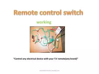
This circuit can be Connect to any of Our home appliances (lamp, fan, radio, etc) to make the appliance turn on/off from a TV, VCD or DVD remote control. The circuit can activated from up to 10 meters. www.Engg-Know.com
38kHz infrared (IR) rays generated by the remote control are received by IR receiver module TSOP1738 of the circuit. Pin 1 of TSOP1738 is connected to ground, pin 2 is connected to the power supply through resistor R5 and the output is taken from pin 3. The output signal is amplified by transistor T1 (BC558). www.Engg-Know.com
The amplified signal is fed to clock pin 14 of decade counter IC CD4017 (IC1). Pin 8 of IC1 is grounded, pin 16 is connected to VCC connect and pin 3 is connected to LED1 (red), which glows to indicate that the appliance is ‘off.’ www.Engg-Know.com
The output of IC1 is taken from pin 2. LED2 (green) connected to pin 2 is used to indicate the ‘on’ state of the appliance. www.Engg-Know.com
Transistor T2 (BC548) connected to pin 2 of IC1 drives relay RL1. Diode 1N4007 (D1) acts as a freewheeling diode. The appliance to be controlled is connected between the pole of the relay and neutral terminal of mains. It gets connected to live terminal of AC mains via normally opened (N/O) contact when the relay energizes. www.Engg-Know.com
Special thanks for : Dr. Farial Al Gabre . The Supervisor of The Electronics Engineering and Communications Department This Project is Prepared By : 1. Ala’a Mohammed Ali 95112. www.Engg-Know.com