Download
1 / 1
10 likes | 90 Vues
Abstract.

E N D
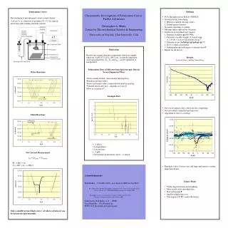
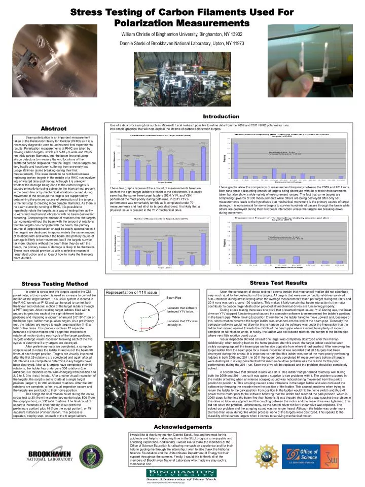
Abstract Beam polarization is an important measurement taken at the Relativistic Heavy Ion Collider (RHIC) as it is a necessary diagnostic used to understand final experimental results. Polarization measurements at RHIC are taken by moving carbon targets, which are 5-10 mm wide and 20-25 nm thick carbon filaments, into the beam line and using silicon detectors to measure the end locations of the scattered carbon displaced from the target. These targets are very fragile and have been suffering from extremely low usage lifetimes (some breaking during their first measurement). This issue needs to be rectified because replacing broken targets in the middle of a RHIC run involves lots of wasted time and money. Although it is unknown whether the damage being done to the carbon targets is caused primarily by being subject to the intense heat present in the beam line or by mechanical vibrations caused during movement of the structure the targets are supported by, determining the primary source of destruction of the targets is the first step to creating more durable filaments. As there is no beam currently running in RHIC, it is possible to repeatedly rotate the targets as a way of testing their ability to withstand mechanical vibrations with no beam destruction occurring. Comparing the amount of rotations that the targets can complete without the beam with the amount of rotations that the targets can complete with the beam, the primary source of target destruction should be easily ascertainable; if the targets are destroyed in approximately the same amount of rotations with and without the beam, the primary cause of damage is likely to be movement, but if the targets survive far more rotations without the beam than they do with the beam, the primary cause of damage is likely to be the beam. These tests should provide us with a definitive reason of target destruction and an idea of how to make the filaments more durable. Use of a data processing tool such as Microsoft Excel makes it possible to refine data from the 2009 and 2011 RHIC polarimetry runs into simple graphics that will help explain the lifetime of carbon polarization targets. These graphs allow the comparison of measurement frequency between the 2009 and 2011 runs. Both runs show a disturbing amount of targets being destroyed with 50 or fewer measurements taken but also show a wide variety of measurement ranges. The fact that some targets are completing upwards of 300 measurements while others are being destroyed after only 50 measurements leads to the hypothesis that mechanical movement is the primary source of target damage. It is nonsensical for some targets to survive hundreds of passes through the beam while others are destroyed during their first beam interaction unless the targets are breaking down during movement. These two graphs represent the amount of measurements taken on each of the eight target ladders present in the polarimeter. It is easily seen that the same three target ladders (B2H, Y1V, and Y2H) performed the most poorly during both runs. In 2011 Y1V’s performance was remarkably terrible as it completed under 70 measurements and had all of its targets destroyed. It is likely that a physical issue is present in the Y1V mechanical drive. Stress Testing Method In order to stress test the targets used in the CNI polarimeter, a Linux system is used as a means to control the motion of the target ladders. This Linux system is located in the RHIC tunnels at IP 12 and can be used to control both the linear and rotational motion of the target ladders through a PET program. After installing target ladders filled with 6 unused targets into each of the eight different ladder positions and imposing a vacuum of around 3.0*10^-7 torr on the beam pipe, ladder manipulation begins. As a preliminary test, the ladders are moved to each target position (1-6) a total of five times. This process involves 12 separate instances of linear motion and 6 separate instances of rotational motion during each cycle of the target positions. Targets undergo visual inspection following each of the five cycles to determine if any targets are destroyed. After preliminary tests are completed, a computer script is used to rotate the ladder in and out of the beam 50 times at each target position. Targets are visually inspected after the first 25 rotations are completed and again after all 50 rotations are complete to determine if any targets have been destroyed. After all 6 targets have completed their 50 rotations, the ladder has undergone 306 rotations (the additional six rotations come from changing from position 1 to 2, 2 to 3, 3 to 4 etc.) in total. After another visual inspection of the targets, the script is set to rotate at a single target position (target 1) for 200 additional rotations. After the 200 rotations are complete, a final visual inspection occurs and the targets are sent back to their home position. This brings the final rotation count during the entire stress test to 30 (from the preliminary portion) plus 506 (from the script portion), or 536 total rotations. The final count of separate instances of linear motion is 60 (from the preliminary portion) plus 14 (from the script portion), or 74 separate instances of linear motion. This process is repeated, step by step, on each of the 8 target ladders. Stress Test Results Beam Pipe Upon the conclusion of stress testing it seems certain that mechanical motion did not contribute very much at all to the destruction of the targets. All targets that were run on functional drives survived 500+ rotations during stress testing while the average measurements taken per target during the 2009 and 2011 runs was only around 100 rotations. This makes it fairly certain that beam interaction is the major contributor to carbon target destruction provided all mechanical drives are functioning properly. During stress testing there was one drive that presented major issues: Y1V. During use, the linear drive on Y1V stopped functioning and caused the computer software to misrepresent the ladder’s position in the beam pipe. While moving to position 2 from home the ladder failed to move upward and, because of this, when rotation occurred the target ladder was smashed into the wall of the beam pipe. Generally the computer software would not allow for this to happen but the software was under the impression that the ladder had moved upward towards the middle of the beam pipe where it would have plenty of room to complete its full rotation when, in reality, the ladder was still located towards the bottom of the beam pipe where very little rotation could occur. Visual inspection showed at least one target was completely destroyed after this mishap. Additionally, when rotating back to the home position after this crash, the target ladder could be seen visibly scraping against the beam pipe on the side opposite from where it had crashed. After removing the target ladder from the beam pipe for a closer inspection it was recorded that all 6 targets had been destroyed during this ordeal. It is important to note that this ladder was one of the most poorly performing ladders in both 2009 and 2011. In 2011 the ladder only completed 64 measurements before all targets were destroyed. It is very possible that this mechanical drive problem was the reason for the poor performance during the 2011 run. Soon the drive will be replaced and the problem should be completely solved. A second drive that showed issues was B1H. This ladder had performed relatively well during both the 2009 and 2011 runs so it was quite a surprise to see problems with it. The problem occurred in the middle of testing when an intense scraping sound was noticed during movement from the park 2 position to position 6. This scraping caused some vibrations in the target ladder and also confused the software by throwing the encoder from the position of the ladder. This caused problems when trying to return the ladder to the park position from position 6; the ladder would hit the home switch and thus kill power to the motor prior to the software believing that the ladder had reached the park position, which is 2000 steps further into the beam line than home is. It was thought that slipping was causing the problem in this drive so lube was applied and the coupling between the motor and the linear drive was tightened. This did not solve the problem, unfortunately, so the control driver for B1H linear drive was replaced. This solved our problem and the scraping sound was no longer heard. Although the ladder was under more distress than usual during this whole process, none of the targets were destroyed. This speaks to the durability of the carbon targets when it comes to surviving mechanical motion. Location that software believed Y1V to be. Location that Y1V was actually in. Stress Testing of Carbon Filaments Used For Polarization Measurements William Christie of Binghamton University, Binghamton, NY 13902 Dannie Steski of Brookhaven National Laboratory, Upton, NY 11973 Introduction Representation of Y1V issue Acknowledgements I would like to thank my mentor, Dannie Steski, first and foremost for his guidance and help in making my time in the SULI program an enjoyable and enriching experience. Additionally, I would like to thank the members of the Office of Science Education for allowing me such an experience and for their help in guiding me through the internship. I wish to also thank the National Science Foundation and the United States Department of Energy for their support throughout the summer. Finally, I would like to thank all of the members of Brookhaven National Laboratory who made my stay such a memorable one. (http://casd.binghamton.edu/files/HiresBUlogo.jpg)