Download
1 / 40
400 likes | 634 Vues
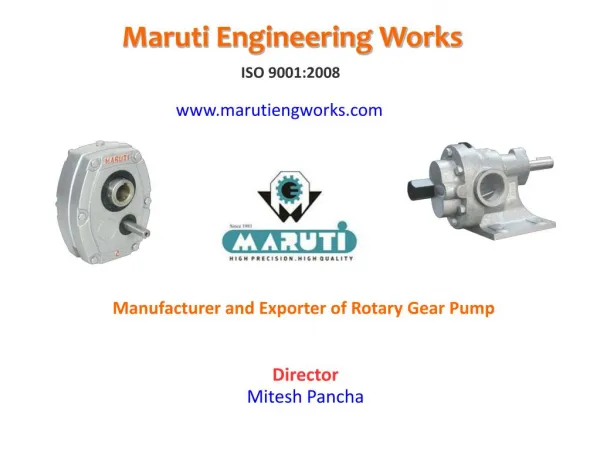
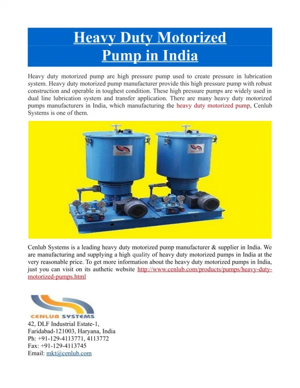
Heavy Duty Gear Pumps Positive Displacement Rotary Twin Gear Pumps Type AERN Series Pumps are Useful for Pumping and Transfer of all kind of Viscous Liquids and Petroleum Products.

E N D
INDEX Chapter Page No. 1 Introduction 1 2 Performance Characteristics 5 3 Operation 8 4 Shaft Sealing 16 5 Installation 17 6 Routine Maintenance Instructions 23 7 Trouble Shooting 24 8 Parts List 26 9 Assembly & Disassembly Instructions 27 10 Dimension Drawing 35 11 Warrantee & Test Certificate 36
Introduction 1 1.1 General This instruction manual contains necessary information on the AERN series pumps having pump model of AERX, AERN & AERB and must be read carefully before installation, service and maintenance. The manual must be kept easily accessible to the operator. Important The pump must not be used for other purposes than recommended and quoted for without consulting the company or your local distributor. Liquids not suitable for the pump can cause damages to the pump unit, with a risk of personal injury. 1.2 Reception, handling and storage 1.2.1 Reception Ÿ Remove all packing materials immediately after delivery. Check the consignment for damage Immediately on arrival and make sure that the name plate/type designation is in accordance with the Packing slip and your order. Ÿ In case of damage and/or missing parts, report immediately to the carrier at once. Notify your supplier. Ÿ All pumps have the serial number stamped on a name plate. 1
Introduction 1 1.2.2 Handling Ÿ Check the weight of the pump unit. All parts weigh- ing more than 20 kg must be lifted using lifting slings and suitable lifting devices, e.g. overhead crane or industrial truck. See section 10 Weights. Never lift the pump unit with only two fastening points. Incorrect lift can cause personal injury and/or damage to the pump unit. Ÿ Always use two or more lifting slings. Make sure they are secured in such away as to prevent them from slipping. The pump unit should be in a straight fashion. Ÿ 2
Introduction 1 1.2.3 Storage Ÿ After receipt of Material and inspection if the pump is not to be installed immediately the pump should be re-packed and placed in suitable places. The following points should be noted: Ÿ Cover the pump with corrosion inhibiting treatment material. Ÿ Storage location free from, dust, moist and vibration free place. Ÿ Rotate the pump unit by hand weekly, to prevent jamming and damaged. 1.3 Safety Ÿ The pump must not be used for other purposes than recommended and quoted for without consulting the company or your local distributor. Always wear suitable safety clothing when handling the pump. Anchor the pump properly before start-up to avoid personal injury and/or damage to the pump unit. Check to see that the pump can be drained without injuring anyone and without contaminating the environment or nearby equipment. Ÿ Ÿ 3
Introduction 1 Make sure that all movable parts are properly covered to avoid personal injury. All electrical installation work must be carried out by electric personnel. Improper installation can cause fatal injuries. Dust, liquids and gases that can cause overheating, short circuits, corrosion damage and fire must be kept away from motors and other exposed equipment. If the pump handles liquids hazardous for person or environment, some sort of container must be installed into which leakage can be led. All (possible) leakage should be collected to avoid contamination of the environment. If the surface temperature of the system or parts of the system exceeds 60°C, these areas must be marked with warning text reading "Hot surface" to avoid burns. Ÿ Ÿ Ÿ Ÿ Ÿ Ÿ 4
Performance Characteristics 2 2 Performance Characteristics 2.1 capacity Ÿ Drop of capacity with increase in pressure & change of liquid viscosity 2.2 suction pressure The identification of suction pressure requirement is significant in any pump application. Ÿ Its calculation helps to find out the suction lift of the pump, which enables to varify whether the pump will be able to self prime or not. Ÿ The suction pressure or termed as NPSH ( Net Positive Suction Head ) can be calculated by following equation NPSH = Atmospheric pressure + Static Head - Static Lift STATIC LIFT ATMOSPHERIC PRESSURE STATIC HEAD 5
Performance Characteristics 2 2 2.3 Discharge pressure: Ÿ The discharge pressure shown in the delivery line is nothing but the overcoming of system pressure created by the resistance of the pipeline and the shearing force of the liquid. Thus it can be said that a gear pump does not develop pressure by its own but work against the system pressure exerted on it. 2.4 Power Consumption: The power consumption of a rotary gear pump is mainly influenced by the differ- ential pressure exerted on it. Factors effecting on power consumption as follows: liquid viscosity Sp. gravity of liquid. Frictional loss. operating temperature Ÿ Ÿ 1. 2. 3. 4. 6
Performance Characteristics 2 THEORITICAL 500 SSU 200 SSU 2.5 Effect of Viscosity: Ÿ Viscosity is that property of any liquid which tends to resist a shearing force. Ÿ The change in viscosity very much affects the perfor- mance characteristics of the pump i.e. capacity, power consumption and speed. Ÿ At a defined set pressure the capacity of a pump slightly reduces with decrease in viscosity. This may be due to increase in internal slippage. Ÿ For a pump running at set speed for the desired capacity, the power consumption increases with increase of liquid viscosity and decreases with the decrease of viscosity. Ÿ The above curves also show the effect of speed with reference to viscosity. CAPACITY VOLUME TRIC LOSSES ACTUAL OEFFERNTIAL PRESSURE CAPACITY ACTUAL THEORITICAL 500 SSU 200 SSU SPEED POWER CONSUPTION HYDRAULIC HP + VOLUMETRIC LOSSES FRICTIONAL LOSSES + MECHANICAL LOSSES POWER CONSUPTION AN NO LOAD = OEFFERNTIAL PRESSURE POWER CONSUPTION ACTUAL 500 SSU 200 SSU THEORITICAL SPEED 7
Operation 3 3.1 Genral Pump Casing Gears Wear Plate Seal Drive Shaft Bearing R.V. Cover Front Cover Relief Valve 8
Operation 3 3.2 Operating Principal The external gear pump uses two identical gears rotating against each other one gear is driven by a motor and it in turn drives the other gear. Each gear is supported by a shaft with bearings on both sides of the gear. 1. As the gears come out of mesh, they create expanding volume on the inlet side of the pump. Liquid flows into the cavity and is trapped by the gear teeth as they rotate. 2. Liquid travels around the interior of the casing in the pockets between the teeth and the casing it does not pass between the gears. 3. Finally, the meshing of the gears forces liquid through the outlet port under pressure. Suction Discharge Suction Discharge Discharge Suction 9
Operation 3 3.3 Safety Relief valve: 3.3.1 Working Principle Ÿ valve protecting the pump against overpressure. Ÿ It can be installed on the pump or in the installation. Ÿ This safety relief valve limits the differential pressure (Δp) between suction and discharge, not the maximum pressure within the installation. For example, as media cannot escape when the discharge side of the pump is obstructed, an over-pressure may cause severe damage to the pump. The positive displacement principle requires the installation of a safety relief The safety relief valve provides an escape path, rerouting the media back to the suction side when reaching a specified pressure level. Ÿ The safety relief valve protects the pump against over-pressure only in one flow direction. The safety relief valve will notprovide protection against over-pressure when the pump rotates in the opposite direction. Ÿ Ÿ 10
Operation 3 An open safety relief valve indicates that the installation is not functioning Ÿ properly. When the safety relief valve is not installed on the pump, other protections against overpressure have to be provided. If the pump rotates in the opposite direction, the safety relief valve or top cover must be disassembled and turned around by 180°. Ÿ Ÿ Suction Discharge Suction Discharge Clockwise Direction Anti Clockwise Direction 11
Operation 3 3.3.2 Safety Relief valve adjustment: Ÿ sure is performed at the factory. Ÿ To adjust the Safety Relief valve for oper- ating pressure, proceed as follows : 1. Open the hex cap. 2. Tighten the ad. screw for increase set operating pressure or loose the ad. Screw for reduce the pump operating pressure. Adjustment of the standard setting pres- ▲ while increase of operating pressure, power consumption of pump must not exceed the motor rated power. 3. Tighten the hex cap. Make sure that air must leakge from hex cap & ad, screw. 12
Operation 3 3.4 Check list for starting the pump: 3.4.1 Cleaning the pump There may be residual mineral oil inside the pump deriving from the pump testing and the initially lubricating of the bearing bushes. If the lubricating oil is not acceptable for the pumped liquid, the pump should be cleaned thoroughly. Ÿ Ÿ 3.4.2 Supply and discharge line Ÿ Suction and discharge pipes are cleaned. Ÿ Suction and discharge pipes are checked for leaks. Ÿ Suction pipe is protected to entered foreign bodies. 13
Operation 3 3.4.3 Characteristics Ÿ Ÿ Pump model see name plate, RPM, working pressure, effective power, working temperature, direction of rotation, NPSHr etc. as per application The characteristics of the pump unit and safety relief valve to be checked. 3.4.4 Electrical installation Ÿ Electric motor rating as per application data sheet Ÿ Electrical installation is complete as per local regulations Ÿ Motor voltage corresponds with mains voltage. Check terminal board. Ÿ Motor protection is adjusted properly. Ÿ Direction of motor rotation corresponds with direction of pump rotation. 14
Operation 3 3.4.5 Safety relief valve Ÿ Ÿ Position of Safety relief valve according to direction of flow. Ÿ The set pressure of the safety relief valve is checked. Safety relief valve (on pump or in piping) is installed 3.4.6 Drive Ÿ Alignment of pump, motor, gearbox etc. is checked 3.4.7 Protection Ÿ All guards and safety devices (coupling, rotating parts, excessive temperature) are placed. 15
Shaft Sealing 4 4. Shaft Seals: 6 6 1 1 7 7 Differnets type of sealing options are aviallable as under. 1. Rubble oil seals 2. Gland Packing 3. Mechanical seal 2 2 5 5 Mech. Seal Mech. Seal 3 3 4 4 Mech. Seal Part List Stationary Resting Part 1 7 1 spring 6 1 O"Ring 5 4 1 Stationary Outer Ring 1 3 Stationary Face 1 2 Rotary Face Rubber Oil Seal & Gland Packing L-Ring 1 1 16
Installation 5 5. Installation: 5.1 General: Pump performance is also dependence on pump installation. This manual gives basic information which is to be observed during installation of the pump. It is important to read this manual by responsible person before installation. 5.2 Location & Foundation: Ÿ Locate the pump/pump unit as close as possible to the liquid source and if possible below the liquid supply level. The better the suction conditions, the better the performance of the pump. Ÿ The pump should always be located where it is accessible for inspection, main- tenance and repairing. Ÿ Every pump should be provide a good foundation by any strong structure to hold the pump rigid and to absorb any strain or shock that may be encountered. If a separate foundation is provided, make it at least 4” wider and longer than base frame. Ÿ When the unit is placed on the foundation, it should be leveled and checked for position against the piping layout and then fastened Owen. 17
Installation 5 5.3 Alignment: Ÿ get the required speed. Ÿ The coupling may be direct drive or belt drive. However direct drive is preferred over belt drive to reduce load on pump drive shaft and bearings. Ÿ During the operation shock load is produce due to pulsation. Therefore, chose the coupling 1.5 time higher ration than normal constant load. Ÿ Pump and drive unit alignment must not more than as shown in fig. For running the pump, it is required to couple pump with the drive unit to 0.200mm Parralel alignment 18
Installation 5 5.4 Piping: Ÿ Use piping with an equal diameter than the con- nection ports of the pump and shortest possible. If the fluid to be pumped is high viscous, pressure losses in the suction and discharge lines may increase considerably. Other piping components like valves, elbows, strainers and filters also cause pressure losses. Diameters, length of piping and other components should be selected in such a way that the pump will operate without causing mechanical damage to the pump/pump unit, taking into account the minimum required inlet pressure, the maximum allowable working pressure and the installed motor power. Check the tightness of the pipes after connection. Ÿ Isolation valve Pump Suction Strainer Ÿ Ÿ 19
Installation 5 5.4.1 Suction piping Ÿ level, the inclining pipe should rise upwards towards the pump without any air pockets. Ÿ A too small diameter or a too long suction pipe, a too small or blocked strainer will increase pressure losses so that the NPSHa (NPSH available) becomes smaller than the NPSH (NPSH required). Cavitations will occur, causing noise and vibrations. Mechanical damage to pump and pump unit is not excluded. Ÿ When a suction strainer or filter is installed pressure losses in the suction line must be checked constantly. Also check if the inlet pressure at the suction flange of the pump is still sufficiently high. Liquids should enter the pump from a level higher than the pump 20
Installation 5 5.4.2 Isolating valves Ÿ Isolation can be done by installing valves in suction and discharge lines. Ÿ These valves must have a cylindrical passage of the same diameter of the piping. Ÿ When operating the pump, the valves must be opened completely. The output must never be regulated by means of closing valves in suction or discharge pipes.It must be regulated by changing shaft speed or by re-routing the media over a by-pass back to the supply tank. 5.4.3 Strainer Ÿ Foreign particles can seriously damage the pump. Avoid the entry of these particles by installing a strainer. Ÿ When selecting the strainer attention should be given to the size of the openings so that pressure losses are minimized. The cross-sectional area of the strainer must be three times that of the suction pipe. Ÿ Install the strainer in such a way that maintenance and cleaning are possible. Ÿ Make sure that the pressure drop in the strainer is calculated with the right viscosity. Heat the strainer if necessary to reduce viscosity and pressure drop. To allow proper maintenance it is necessary to be able to isolate the pump. 21
Installation 5 5.5 Electrical Installation. Ÿ Ÿ Input voltage & frequency must be match with operating drive motor. Ÿ Install electrical overload safety device. Make sure that electrical connection must be properly. 22
Routine Maintenance instructions 6 6 Routine Maintenance instructions: Ÿ Ÿ Temperature of pump body should not exceed the operating temperature. Ÿ Check the leakage from suction and delivery line. Ÿ Check leakage from gland packing or shaft seal. Ÿ Check the air leakage from suction and relief valve. Ÿ Check the power consumption. Ÿ Check the temperature of the drive unit. Ÿ Check the alignment of the pump unit. Ÿ Check the axial and radial play of drive shaft Check the nose of pump, Noise must not abnormal. 23
Trouble Shooting Trouble Shooting 7 Problem Prime lost after starting Excessive power absorbed Pump stalls when starting Low discharge pressure Mechanical seal leakage Packed gland leakage Pump will not prime Noise and vibration Irregular discharge Pump element wear Motor overheats Pump overheats Under capacity No flow Seizure Probable Causes Solutions Reverse motor. Expel gas from suction line and pumping chamber and introduce fluid. Increase suction line diameter. Increase suction head. Simlify suction line configuration and resuce length. Reduce pump speed. Incorrect direction of rotation Pump not Primed. Insufficient NPSH available. (Cavitation) Fluid vaporising in suction line. Increase suction line diameter. Increase suction head. Simplify suction line configuration and reduce length. Reduce pump speed. Remake pipework joints. Service fittings. Increase fluid temperature. Decrease pump speed. Check seal face viscosity limitations. Decrease Fluid temperature. Increase pump speed. Cool the pump casing. Reduce fluid temperature. Check seal face and elastomer temp. limitations. Heat the pump casing. Increase fluid temperature. Clean the system. Fit strainer to suction line. Check for obstructions i.e. closed valve. Service system and change to prevent problem recurring. Simplify dicharge line to decrease pressure. Slacken and re-adjust gland packing. adjust gland packing. Decrease pump speed. Increase pump speed. Check alignment of pipes. Fit flexible pipes or expansion fittings. Support pipework. Check alignment and adjust mountings accrdingly. Fit lock washers to slack fasteners and re-tighten. Refer to pump maker for advice and replacement parts. Refer to pump maker's instructions. Check rated and duty presures. Refer to pump maker. Fit new components. Air entering suction line. Strainer or filter blocked. Fluid viscosity above rated figure. Fluid viscosity below rated figure. Fluid temp. above rated figure. Fluid temp. below rated figure. Unexpected solids in fuid. Discharge pressure above rated figure Gland over-tightened Gland under-tightened Pump speed above rated figure. Pump speed below rated figure. Pump casing strained by pipework. Flexible coupling misaligned. Insecure pump drive mountings. Shaft bearing wear or failure. Insufficient gearcase lubrication. Metal to metal contact of pumping element. Worn pumping element. Relief valve leakage. Check pressure setting and re-adjust if necessary. Examine and clean sealing surfaces. Replace worn parts. Check for wear on sealing surfaces etc. Replace if necessary. Relief valve chatter Suction lift too high. Fluid pumped not compatible with materials used No barrier system to prevent flow passing. Pump allowed to run dry. Lower pump or raise liquid level. Use optional materials. Ensure discharge pipework higher than suction tank. Ensure system operation prevents this. Fit single or double flushed mechanical seals. Fit flushed packed gland. Check and replace motor bearings. Fit pumping element. Faulty motor. Pumping element missing 24
18 2 3 17 4 16 5 6 7 9 15 29 8 10 12 11 14 13 19 20 21 22 23 24 1 25 26 28 27 25
Parts List 8 AERN PUMP AERX PUMP AERB PUMP AERN PUMP AERX PUMP AERB PUMP PARTS NO. 1 2 3 4 5 6 7 8 9 10 11 12 13 14 PARTS NO. 15 16 17 18 19 20 21 22 23 24 25 26 27 28 29 DESCRIPTIONS DESCRIPTIONS Stator shaft Rotor shaft Bearing Sleeve Snap Ring Washer, Gear Shaft Assembly Bolt, Gear Shaft assembly Pump Casing R. V. Cover Hex Cap, Relief Valve Adjustment screw R. V. Plug Spring Sheet R. V. Spring R. V. Piston Front Cover Drain oil plug Bolt, gland cover washer, gland cover Gland cover Shaft Seal Bolt, Front cover Washer, front cover Dowel Oil inlet plug Shaft Bearing V - seal Wear Plate Body Packing Gears AERN Pump with Needle Roller bearing as shaft Bearings AERX Pump with Needle Roller bearing as shaft Bearings & V-seal AERB Pump with Bush bearing as shaft Bearings 26
Assembly & Disassembly Instructions 9 9.1 General Ÿ tioning, high repair costs and long-term inoperability. Ÿ Disassembly and assembly may only be carried out by trained personnel. Such personnel should be familiar with the pump and follow the instructions below. Ÿ ANI Engineers is not liable for accidents and damage of the pump or pump unit for faulty assembly. Ÿ Remove the pump from the operation. Insufficient or wrong assembly and disassembly can lead to the pump malfunc- 9.2 Dissemble Instructions. 9.2.1 Remove gland cover Ÿ unscrew hex bolt no.2 & washer Ÿ Remove gland cover 2 4 27
Assembly & Disassembly Instructions 9 9.2.2 Remove Front cover Ÿ Ÿ Open front cover Ÿ Remove body packing Ÿ Remove dowel if inside the front cover. Ÿ Remove V-seal if pump model AERX Ÿ Remove shaft bearing (Needle roller or bush ) Ÿ Remove shaft seal from front cover,no.5 unscrew hex bolt no.6 & washer 5 6 9.2.3 Remove R.V. cover assembly Ÿ unscrew hex bolt no.6 & washer Ÿ Remove R.V. cover Ÿ Remove body packing Ÿ Remove dowel if inside the R.V. cover. Ÿ Remove V-seal if pump model AERX Ÿ Remove shaft bearing (Needle roller or bush ) 6 28
Assembly & Disassembly Instructions 9 9.2.4 Relief valve disassembly Ÿ find problem in relief valve operation. Ÿ unscrew hex cap, no.23 Ÿ unscrew Adjustment screw Ÿ Open relief valve plug Ÿ Remove spring sheet Ÿ Remove spring Ÿ Remove piston. Open relief valve assembly if 23 29
Assembly & Disassembly Instructions 9 9.2.5 Remove Gear shaft assembly Ÿ Ÿ Remove rotor and stator gear shaft assembly. Remove wear plates PRESS 9.2.6 Gear shaft disassembly Ÿ Unscrew bolts no. 20 Ÿ Remove washers, no. 19 Ÿ Remove gears & Bearing Sleeves from shafts, use the plastic block to avoid shaft must not damage from press force. SUPPORT 30
Assembly & Disassembly Instructions 9 PRESS 9.3 Assembly Instructions. 9.3.1 Gear shaft assembly Ÿ hand & second is left hand in pair) Ÿ Insert bearing sleeve both side, replace if damage Ÿ Insert washer and screw the bolt no. 20 Insert Gears in the shafts (one gear is right SUPPORT 9.3.2 Gear shaft assembly Ÿ Assembled rotor & stator gear shaft assembly in pump casing. Ÿ Assembled wear plate, replace wear plates if wear out. Ÿ Replace gasket body packing with seal- ant. 31
Assembly & Disassembly Instructions 9 9.3.3 Relief valve assembly Ÿ Ÿ Place spring in piston. Ÿ Place spring sheet on spring Screw the relief valve plug. Ÿ Screw the adjustment screw as previously. Ÿ Screw the hex cap over the adjustments screw. Place piston in relief valve cover. 9.3.4 Relief valve cover assembly Ÿ Fit the bearing in Relief valve cover. ,replace bearing if damaged Ÿ Fit the V-seal in Relief valve cover if pump model is AERX. (replace the V-seal if damaged) Ÿ Fit the relief valve assembly with pump casing. Ÿ Screw the bolt no. 6 with washer 6 32
Assembly & Disassembly Instructions 9 9.3.5 Front cover assembly Ÿ bearing if damaged) Ÿ Fit the V-seal in front cover if pump model is AERX. (replace the V-seal if damaged) Ÿ Fit the front cover assembly with pump casing. Ÿ Screw the bolt no. 6 with washer Fit the bearing in front cover. (replace 9.3.6 Pump Rotation Check: Ÿ Checks the drive shaft rotates smoothly, then fit all dowel and tighten the bolt no. 6. 5 6 33
Assembly & Disassembly Instructions 9 9.3.7 Gland cover Fitting: Ÿ (replace the seal if damaged) Ÿ Push the gland cover in to the gland box. Ÿ Screw the bolt no 2. With washer. (each bolt should b tighten equally) Fit the shaft seal in gland cover. 2 4 34
Dimension Drawing 10 OVERALL DIMENTIONS A F MOUNTING DIMENSIONS FLANGE DIMENSIONS No. OF HOLE SHAFT DIMENSIONS Weight Model No. OF SIZE Dø L1 H2 H1 D ø 1 D ø 2 L B C E H T P.C.D. P O Kg. AE-050-S-M-L AE-100-S-M-L AE-150-S-M-L AE-200-S-L AE-250-S-L AE-300-S-L AE-400-S-L AE-500-S-L AE-600-S-L AE-601-S-L 239 271 318 359 419 461 554 615 690 749 150 160 180 200 220 240 280 295 340 360 110 130 145 165 190 220 255 280 318 357 80 90 100 110 130 150 160 220 270 300 350 380 91 80 90 69.0 74.0 80.0 89.5 100.0 131.0 145.0 160.0 178.0 200.0 12 12 14 14 15 20 22 25 26 28 08 10 10 12 15 18 18 19 20 22 4 4 4 4 4 4 4 4 4 4 89 16 16 16 19 19 19 19 22 22 22 60 79 98 22 25 25 40 40 53 53 60 70 70 30 30 40 50 55 60 65 85 95 100 11.5 15.0 21.0 24.0 27.0 32.0 37.0 47.0 52.0 57.0 4 5 6 8 8 13.0 17.0 23.5 27.0 30.0 35.0 40.0 50.5 58.0 61.0 8.0 14.0 22.5 28.0 43.0 59.0 82.0 150.0 175.0 190.0 100 119 133 163 166 189 215 215 230 108 127 152 178 190 229 254 279 279 105 110 130 160 180 200 220 240 100 112 132 160 180 200 225 250 121 140 152 190 216 241 241 10 10 14 16 16 A F L1 L P DØ Q H2 D Ø 2 H H1 C E T B 4 Nos D 1Ø Holes 35
11 36