Download
1 / 18
180 likes | 182 Vues
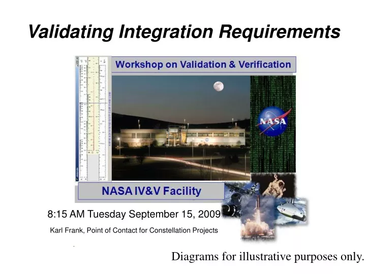
Validating Integration Requirements. 8:15 AM Tuesday September 15, 2009 Karl Frank, Point of Contact for Constellation Projects. Diagrams for illustrative purposes only. Scope. Software components Documents explicitly labeled as Integration Requirement Docs

E N D
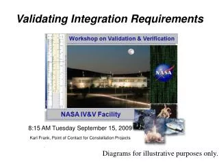
Validating Integration Requirements 8:15 AM Tuesday September 15, 2009 Karl Frank, Point of Contact for Constellation Projects Diagrams for illustrative purposes only.
Scope • Software components • Documents explicitly labeled as Integration Requirement Docs • Software Component Requirement Docs containing specifications for software interfaces • We don’t validate hardware interfaces • Software interfaces: concept here is fundamentally different. Requirements for data consistency, for example, in software interfaces, are special
Evolution of an approach • First iterations of behavior modeling included communication diagrams representing interactions among systems shown as objects • Showed scenarios of message exchange (requests for services, broadcasts of status data, etc.) passed between systems – as well as physical exchanges: Breathing Air, Power • Messages descriptive text • Particular sender owned messages, represented as labeled lines between objects
Specialized Comm Diagrams • Next iterations of communication diagrams representing interactions between systems concealed the actual destinations in the interest of platform independent view • Messages still descriptive text on lines, not first-class model elements • As a view of an interaction, still owned by the sender, and not re-assignable as services to another interface of another component.
Goal: move to service contract • Particular component ownership of services of no interest, indeed an obstacle because a design specific feature • Desire to use design-by-contract concepts • Specify Interfaces without hard commitment to what component provides the interface • Model services in a way that allows moving them around in the model and associating them with design-by-contract properties
UML interface concept provides that! • Early proposal to use a text document with a common template, for defining interfaces and service contracts • UML 2 already provide these concepts • Not surprising since the language was designed to support software engineering needs. • Interfaces and services with contracts maintained in the model • Reassign by drag and drop as needed
Model as Database of Interfaces • Drag desired interface onto diagrams as needed, associate with any component • Move selected services between interfaces, without having to redefine their associated contracts
Name alone doesn’t tell if an interface will meet expectations A Control that actually ignites an engine is very different from status query that reports if its running
Completeness Audits Which components require? Which provide? That service? Ensure there is a provider for every required service • A particular service • Ensure that there is a consumer for every provided service UML model (not diagrams) can automate queries on model database to discover gaps and mismatches
Consistency Audits Exactly how does the provider define Exactly what data does the consumer expect? A way to specify that exactly the same details are supported on both sides of the interface • Detailed specifications of data is supported, not just names like “Engine Status”
Supports Elaboration Simple view Switch to detailed view Of the same interface, showing details of the services offered • Without “drawing” a new diagram, continuous evolution of more details in the same model
Beyond Behavior • Interaction a UML behavior concept, represented in sequence and communication diagrams, adapted to show temporal sequences, aka scenarios • UML provides static structure and data type modeling, adapted to represent architectural interfaces and to specify data requirements
Advantages of Diagram Choice • Differentiates software architecture components from hardware architecture on which it is deployed. • Distinguishes interfaces provided from interfaces required • Can show the services offered in an interface FSW: Flight Software J2X ECU: Engine Control Unit Spotting inconsistent assignment of a command to a query interface!
Differentiating Hardware and Software Software Component Notation FSW: Flight Software ECU: Engine Control Unit Hardware Deployment Notation
Notation Basics FSW: Flight Software Ports: Represent Interaction Points and control what kind of service or data is made public at that point by the component RIU: remote interface unit