Download

1 / 82
1.38k likes | 2.6k Vues
Lecture 03: Design Loads. By: Prof Dr. Akhtar Naeem Khan chairciv@nwfpuet.edu.pk. Topics to be Addressed. Types of loads Wind Load Earthquake Load Load Combinations. Feeling Responsibility. Types of Loads.

E N D
Lecture 03: Design Loads By: Prof Dr. Akhtar Naeem Khan chairciv@nwfpuet.edu.pk
Topics to be Addressed • Types of loads • Wind Load • Earthquake Load • Load Combinations
Types of Loads • Determination of loads for which a given structure may be designed for is a difficult problem. • Questions to be Answered: • What loads may structure be called upon during its lifetime? • In what combinations these loads occur? • The probability that a specific live load be exceeded at some time during lifetime of structure?
Types of Loads Design load should be rational such that considering 150mph wind load for a tower is reasonable but not the load of a tank on top of the tower.
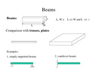
Types of Loads Three broad categories: • Dead load • Live load • Environmental load
Types of Loads • Dead load Dead Loads consist of the weight of all materials and fixed equipment incorporated into the building or other structure. (UBC Section 1602) • Weight of structure • Weight of permanent machinery etc. • Dead loads can be reasonably estimated if the member dimensions and material densities are known.
Types of Loads • Live load: Live loads are those loads produced by the use and occupancy of the building or other structure and do not include dead load, construction load, or environmental loads. • Weight of people, furniture, machinery, goods in building. • Weight of traffic on bridge
Types of Loads Live load: • Buildings serve such diverse purposes that it is extremely difficult to estimate suitable design loads. • Different building codes specify live load requirements. • Uniform Building Code (UBC) • Southern Standard Building Code • BOCA National Building Code
Types of Loads Live load: (UBC Table 16-A)
Types of Loads Live load: The 40psf L.L specified by code for Residential Buildings is too Conservative to account for the uncertainties in structural actions Such as impact, fatigue, temp. effects etc.
Types of loads • Environmental Loads Environmental loads include wind load, snow load, rain load, earthquake load, and flood load.
Live load reduction • The Uniform building code and BOCA National building code permit reduction in basic design live load on any member supporting more than 150ft2 R = r(A-150) Or R = 23.1(1+D/L) Where R = reduction, percent r = rate of reduction = 0.08% for floors A = area supported by floor or member D = dead load, psf L = basic live load,psf
Wind load • Bernoulli’s equation for stream flow is used to determine local pressure at stagnation point, considering air to be non-viscous & incompressible. q: pressure ρ: mass density of air v: velocity q = (ρv2/2) • This pressure is called velocity pressure, dynamic pressure, stagnation pressure. • This equation is based on steady flow. • It does not account for dynamic effects of gusts or dynamic response of body.
Wind load • Resultant wind pressure on body depends upon pattern of flow around it. • Pressure vary from point to point on surface, which depends on shape & size of body. • Resultant wind pressure is expressed as: PD = CDA(ρv2/2) PL= CLA(ρv2/2) CD : Drag coefficient CL : Lift coefficient
Wind load • For buildings bridges and the like pressure is expressed in terms of Shape Factor CS (pressure coefficient) P = CSq = CS(ρv2/2) • Air at 15C weighs 0.0765pcf V: mph P=0.00256CSV2
Wind load • Measured wind velocities are averages of fluctuating velocities encountered during a finite time. • In US average of velocities recorded during the time it takes a horizontal column of air 1 mile long to pass a fixed point. • Fastest mile is highest velocity in 1 day. • Annual extreme mile is the largest of the daily maximums.
Wind load • Wind pressure to be used in design should be based on a wind velocity having a specific mean recurrence interval. • The flow of air close to ground is slowed by surface roughness, which depends on density, size and height of buildings, trees, vegetation etc. • Velocity at 33ft (UBC: Sec 1616) above ground is used as the basic values for design purpose.
Wind load • Shape factor varies considerably with proportion of structure & horizontal angle of incidence of the wind. • CS for windward face of flat roofed rectangular building is 0.9 • CS for negative pressure on rear face varies from -0.3 to -0.6 • For such building resultant pressure be determined by shape factor 1.2 to 1.5 • Commonly used is 1.3 • CS for Side walls -0.4 to –0.8 • CS for roof –0.5 to –0.8
Wind load • Wind forces on trussed structures e.g. bridges, transmission towers, beam bridges, girder bridges etc. difficult to assess because of leeward parts of structure. • Recommended coefficients for walls of buildings, gabled roofs, arched roofs, roofs over unenclosed structures(stadium), chimneys, tanks, signs, transmission towers etc. are given in ASCE 7-02 • Wind pressures specified by building codes include allowance for gust and shape factors.
Wind load • Pressure acts on the windward face of the building • Suction acts on the leeward face of the building • Suction acts on the sides of the building so a person • standing in The window may be thrown outside • Suction acts on the floor so that GI sheet floors are • blown away During strong wind storms
Wind load The revolving restaurant supported by a concrete column will Experience suction which will cause tension in the column and as Concrete is weak in tension so it may crack. As a result the lateral Wind load may collapse the restaurant.
Wind load AASHTO specification for Bridge Truss The pressure face is taken as a solid without openings and suction on the leeward face is neglected (its still quiet Conservative)
Wind Pressure UBC 97 • Design Wind Pressure: UBC (20-1) Ce: combined height, exposure and gust factor (Table 16-G) Cq (or Cs): Pressure coefficient for the structure or portion of structure under consideration (Table 16-H) qs : wind stagnation pressure at the standard height of 33ft (Table 16-F) Iw: importance factor (Table 16-k)
Wind Load Example • Example: Calculate the wind pressure exerted by a wind blowing at 100mph on the civil engineering department old building. Sol: According the formula given above: For windward face: Cs = .8 inward (UBC97 Table 16-H) For Leeward face: Cs = .5 outward (UBC97 Table 16-H) V: mph P=0.00256CSV2
Pwindward = 20.48 psf Pleeward = 12.80 psf Ptotal = 33.28 psf Wind Load Example P=0.00256CSV2
Alternate Method: Ce = 0.76 ( For 30ft height & Exposure B, Table 16-G) Cq = 0.8 ( For windward wall, Table 16-H) = 0.5 ( For leeward wall, Table 16-H) qs = 25.6 psf (For 100mph velocity, Table 16-F) Iw = 1.0 (According to occupancy category, Table16-K) Wind Load Example UBC (20-1)
Pwindward = 15.56 psf Pleeward = 9.73 psf Ptotal = 25.29 psf Wind Load Example
Earthquake Load Earthquake Waves • Earthquake loads are necessary to consider in earthquake prone regions. • Earthquake waves are of two types: • Body waves • Surface waves
Earthquake Load Earthquake Waves • Body waves consists of P-waves & S-waves • These waves cause the ground beneath the structure to move back and forth and impart accelerations into the base of structure. • Period and intensity of these acceleration pulses change rapidly & their magnitude vary from small values to more than that of gravity.
Earthquake Load Earthquake Waves
Earthquake Load Earthquake Waves Body waves reach the buildings first, followed by the more Dangerous surface waves A linear increase in magnitude of EQ causes approximately cubic increase in the corresponding amount of energy released
Earthquake Load Earthquake Waves Shallow EQ of depth, say, 15-20km are far more dangerous than deep EQ of depth, say, 150-200km.
Earthquake Load Factors effecting earthquake response of structures • Structure response to an earthquake primarily depends upon: • Mass • stiffness • natural period of vibration • damping characteristics of structure • location from epicenter • topography & geological formation.
Earthquake Load Factors effecting earthquake response of structures
Earthquake Load Response Modification Factor
Earthquake Load Response Modification Factor
Earthquake Load Natural Time period of structures EQ generally have short periods which may match the natural period of the low rise buildings, say 10 to 20 stories which causes resonance results in serious damages. The possibility of resonance for high rise buildings is low due to longer time periods.
Earthquake Load UBC 97 Static Lateral force procedure: Limitations • 1629.8.3:The static lateral force procedure of Section1630 may be used for the following structures: • All structures, regular or irregular, in Seismic Zone 1 and in Occupancy Categories 4 and 5 in Seismic Zone 2. • Regular structures under 240 feet in height with lateral force resistance provided by systems listed in Table 16-N, except where Section 1629.8.4, Item 4, applies. • Irregular structures not more than five stories or 65 feet • in height
Earthquake Load UBC 97 Static Lateral force procedure: Limitations • 1629.8.3:The static lateral force procedure of Section1630 may be used for the following structures: • Structures having a flexible upper portion supported on a rigid lower portion where both portions of the structure considered separately can be classified as being regular, the average story stiffness of the lower portion is at least 10 times the average story stiffness of the upper portion and the period of the entire structure is not greater than 1.1 times the period of the upper portion considered as a separate structure fixed at the base.
Earthquake Load UBC 97 1630.2.1 Design base shear. The total design base shear in a given direction shall be determined from the following formula: V = (Cv I/R T) * W (30-4) The total design base shear need not exceed the following: V = (2.5 Ca I/R) * W (30-5) The total design base shear shall not be less than the following: V = (0.11 Ca I) W (30-6) In addition, for Seismic Zone 4, the total base shear shall also not be less than the following: V = (0.8 ZNv I/R) * W (30-7)
Earthquake Load UBC 97 1630.2.1 Design base shear. For Seismic Zones 1, 2A, 2B, and 3: V = (0.11 Ca I) W ≤ V = (Cv I/R T) * W ≤ V = (2.5 Ca I/R) * W For Seismic Zone 4: V = (0.11 Ca I) W ≤ V = (Cv I/R T) * W ≤ V = (2.5 Ca I/R) * W V = (0.8 ZNv I/R) * W
Earthquake Load UBC 97 1630.2.1 Design base shear. V = total base shear *Ca& CV = seismic dynamic response spectrum values. (table 16-Q & table 16-R) Z = seismic zone factor. (Table 16.I) Nv & Na = near source factors that are applicable in only seismic zone 4. (Table 16-T & Table 16-S) *Depends on Seismic zone and soil profile
Earthquake Load UBC 97 Soil profiles
Earthquake Load UBC 97 Seismic Zone BCP 07
Earthquake Load UBC 97 1630.2.1 Design base shear. I = Importance factor (Table 16-K) W = Total seismic dead load R = Response factor depends on type of structural system (Table 16-N) T =Elastic fundamental period of vibration. T = Ct hn¾ Ct = 0.035 for steel moment resisting frame
Earthquake Load UBC 97 1630.2.1 Design base shear. (0.11 Ca I): this coefficient is also independent of the period of vibration. It is a lower bound value, keeping V at some minimum value.
Earthquake Load UBC 97 1630.2.1 Design base shear. (Cv I / R T): acceleration factor (also known as a seismic base shear coefficient). This coefficient will govern V for buildings with medium to long fundamental period of vibrations. The forces in these buildings are induced by the velocity component of the bedrock motion. Hence the "v" subscript.