Download
1 / 19
190 likes | 199 Vues
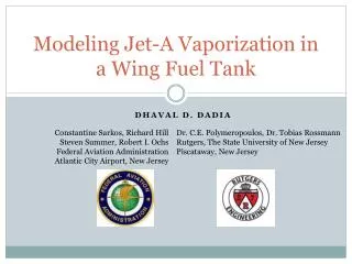
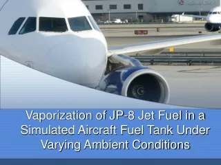
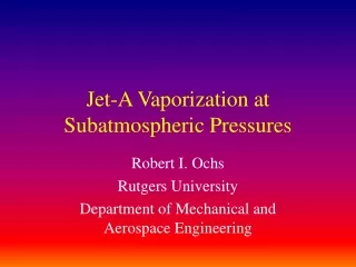
JET A VAPORIZATION IN AN EXPERIMENTAL TANK Part 1 computed results. C. E. Polymeropoulos Department of Mechanical and Aerospace Engineering Rutgers University 98 Bowser Rd Piscataway, New Jersey, 08854-8058, USA Tel: 732 445 3650, email: poly@jove.rutgers.edu. Motivation.

E N D
JET A VAPORIZATIONIN AN EXPERIMENTAL TANKPart 1 computed results C. E. Polymeropoulos Department of Mechanical and Aerospace Engineering Rutgers University 98 Bowser Rd Piscataway, New Jersey, 08854-8058, USA Tel: 732 445 3650, email: poly@jove.rutgers.edu
Motivation • Combustible mixtures can be generated in the ullage of aircraft fuel tanks • Need for estimating temporal dependence of F/A on: • Fuel loading • Temperature for the liquid fuel and tank walls • Ambient pressure and temperature • Time
Previous Work • Measurement of LFL of Jet A using different methods: Nestor (1967), Ott (1970) • Model of vaporization in a fuel tank using single component fuel: Kosvic (1971) • Jet A Explosion Studies: Shepherd, 1997 • Review of Flammability Hazard: DOT /FAA/AR-98/26 • Jet A multi-component, non-equilibrium model: Polymeropoulos and Summer (2002) • etc • Other work not available in the open literature?
Physical Considerations • 3D natural convection heat and mass transfer • Liquid vaporization • Vapor condensation • Variable Pa and Ta • Multicomponent vaporization and condensation • Well mixed gas and liquid phases • Ralullage~o(109) • Raliquid~o(106)
Approach • Use of available empirical or experimental data on temporal variation liquid fuel, and tank wall temperatures • Possible CFD modeling of the 3D coupled heat and mass transfer processes in the tank • Advantages: • Detailed spacial information on conditions within the tank • Disadvantages: • Uncertainties with turbulent modeling of the multi-component mixing processes • Computational complexity with 3D flows • Computational time • Possible use of well mixed tank model with spatially uniform but temporally varying fluid temperatures and compositions • Advantages: • Ease of implementation • Globally correct results provided the fluids are well mixed • Disadvantages • Requires empirical correlations for heat and mass transport • Uncertainties with respect to the degree of well mixedness
Principal Assumptions • Well mixed gas and liquid phases • Uniformity of temperatures and species concentrations in the ullage gas and in the evaporating liquid fuel pool • Use of available experimental liquid fuel, and tank wall temperatures • Quasi-steady transport using heat transfer correlations and the analogy between heat and mass transfer for estimating film coefficients for heat and mass transfer • Liquid Jet A composition form published data from samples with similar falsh points ts those tested
Liquid Jet A Composition • Liquid Jet A composition depends on origin and weathering • Jet A samples with different flash points were characterized by Wodrow (2003): • Results in terms of C5-C20 Alkanes • Computed vapor pressures in agreement with measured data • JP8 used with FAA testing in the range of 120 °F < F.P. < 125 °F • Present results use compositions corresponding to samples with F.P. =120 °F and F.P. = 125 °F from the Woodrow (2003) data
Dry Tank Ullage Temperature Comparison with Experiment(Ochs,2003),Ambient pressure
Dry Tank Ullage Temperature Comparison with Experiment(Ochs,2003),30,000 ft
Computed and Measured (Summer, 1992) Propane Equivalent Hydrocarbon Concentrations Atmospheric Pressure, 2.2 x1.22 x 0.93 m Vented Test Tank with heated floor and unheated walls Tmaxfuel = 52 °C 2 3
Model Predictions for a Given Flight ScenarioTank Dimensions (m): 0.9 W x 0.9 D x 0.6 HJet A. Flash point = 322.2 K (120 °F)
Fuel Vapor Mass Account after LiftoffL=32 Kg/m3, Tfi = 325 K, Tf - Ts = 10 K
F/A Variation during FlightL=400 kg/m3, Tfi = 315 K, Tf-Ts=15 K
Conclusions • The Jet A fuel to air ratio in a test tank can be estimated using spatially uniform but temporally varying properties in the tank • Liquid Jet A can be assumed to consist of a mixture of C5-C20 Alkanes obtained from fuel samples with F.P. in the range of those tested • The computed results appear to agree with previous atmospheric pressure data from a test tank • The model was used for estimating the F/A variation during an example flight scenario. Examples of computed results demosntrate: • The strong effect of liquid temperature on ullage A/F • The considerable temporal variation of ullage species composition • The model results must be compared with measurements appropriate to different flight conditions