Download
1 / 18
240 likes | 605 Vues
COMMUNICATION SYSTEM EECB353 Chapter 2 (VI) AMPLITUDE MODULATION. Dept of Electrical Engineering Universiti Tenaga Nasional. SSB Transmitter.

E N D
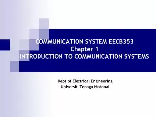
COMMUNICATION SYSTEM EECB353Chapter 2 (VI)AMPLITUDE MODULATION Dept of Electrical Engineering UniversitiTenagaNasional
SSB Transmitter • The design of the SSB transmitter is accomplished in two stages. First we generate a DSBSC signal and then remove the lower sideband to achieve the final SSB result. • Generating the DSBSC Signal • Internally, the balanced modulator generates the AM waveform, which includes the carrier and both sidebands. • It then offers the facility to feed a variable amount of the carrier back into the modulator in anti-phase to cancel the carrier output. • In this way we can balance out the carrier to suppress it completely leaving just the required DSBSC waveform.
Generating DSBSC 450k 453k 456k BM 1 DSBSC 0 3k Audio input Carrier freq, 453kHz
SSB Transmitter • From DSBSC to SSB • The DSBSC signal consists of the two sidebands, one of which can be removed by passing them through a bandpass filter. • The inputs to the balanced modulator comprise the audio inputs from the audio oscillator, which extend from 300Hz to 3.4kHz, and the carrier input. • On the ANACOM 1/1 board this carrier oscillator, although marked as ‘455kHz’, actually needs to operate at a frequency which is a little less than this, around 453kHz. Why is this? • It is to ensure that the upper sideband can pass through the ceramic bandpass filter but the lower sideband cannot pass through.
DSBSC to SSB (1st conversion) 0 3k 450k 453k 456k 453k 456k Audio input BM 1 BPF 1 DSBSC SSBSC Ctr freq = 455kHz BW = 3kHz Carrier freq, 453kHz 453k 455k 456k
SSB Transmitter • The upper sideband can be seen to be within the passband of the ceramic filter but the lower sideband is outside and will therefore be rejected. • The sideband frequencies are quite close to each other and a good quality ceramic filter is required. • A ceramic filter passes only a narrow range of frequencies with a sharp cut-off outside of its passband.
SSB Transmitter • Transmitting the SSB signal – SSB signal that generated before is combined with a 1MHz carrier signal to produce a new DSBSC signal • This signal will now have two new sidebands, • one around 1MHz + 455kHz = 1.455MHz • and the other at 1MHz - 455kHz = 545kHz. • Since these two sidebands are separated by a wide frequency range, the filter design is not critical and a simple parallel tuned circuit is sufficient.
DSBSC to SSB (2nd conversion) 544k 547k 1M 1.453M 1.455M 1.453M 1.456M 453k 456k O/P Amp BM 2 BPF 2 DSBSC SSBSC Ctr freq = 1.455M BW = 3kHz Carrier freq, 1MHz 1.453M 1.455M 1.456M
SSB Transmitter • The 1.455MHz output signal then only requires amplification before transmission. antenna LO =1MHz LO =453kHz Good quality filter audio audio +LO =455kHz 1455kHz
SSB Receiver • The receiver is of the normal superhet design. The first stages are the same as we met for DSBFC. • The incoming signal is amplified by the RF Amplifier and passed to the mixer. • The other input to the mixer is the local oscillator that is running at 455kHz above the frequency to which the receiver is tuned. • The mixer generates sum and difference signals and the lower of the two is the resulting IF signal occupying a range of frequencies around 455kHz. • The audio information must now be separated from these IF frequencies. RF section Mixer IF Section Mixer 2 Audio Amplifier
SSB Receiver • One way of extracting the audio signals is to use a mixer to shift the frequencies. • If a mixer combined an input of (audio + 455kHz) with another input of 455kHz, the resultant outputs would be the usual ‘sum’ and ‘difference’ frequencies. • The ‘sum’ would be (audio + 455kHz) + (455kHz) = (audio + 910kHz) which is far too high a frequency to be of much interest to us. • The ‘difference’ frequency is just what we wanted (audio + 455kHz) - (455kHz) = (audio). LO audio audio + 455kHz audio + 910kHz 455
SSB Receiver • In the ANACOM 1/2, the mixer is called the product detector and the 455kHz input to the product detector is provided by an oscillator called a ‘Beat Frequency Oscillator’ or BFO.
SSB Receiver Sideband inversion Received Signal fIF = fLO + fRF fIF(lsb) = fLO - fRF(usb) = 1.908M – 1.456M = 0.452M fIF(usb) = fLO - fRF(lsb) = 1.908M – 1.453M = 0.455M 1.453M 1.456M 0.452M 0.455M Preselector & RF amp IF Amplifier & BPF Mixer 2 & Product Detector Mixer 1 LPF Audio amp LO BFO 455kHz fLO = fc + fIF = 1.453M + 455k = 1.908MHz SUM : audio + 455 + 455 = XXXX DIFF: audio + 455 – 455 = audio
MT Sem 2 0809 Figure 2: SSB Transmitter • Figure 2 below shows a block diagram of an SSB transmitter. A modulating signal with bandwidth of 3 kHz and centre frequency of 2 kHz as shown is inserted to the first balance modulator input. • What kind of signal generated at the output of the balance modulator 1 (output a). Sketch the spectrum and label the frequencies. [2] • Sketch the spectrum at the output b and output c. Label the frequencies. [3]
Example The SSB Receiver has output at 1 kHz. The carrier used and suppress at the transmitter was 2 MHz, and the upper sideband was utilized. Determine the exact frequency at all stages for a 455 kHz IF frequency.
Example 1. At 100% modulation, an AM signal has a total power of 1200 watts. If it was converted to SSBSC and the sideband component had the same amplitude as before, the total power would be: a. 100 watts. b. 200 watts. c. 400 watts. d 800 watts. 2. The output of a balanced modulator in an SSB transmitter being modulated with a modulating signal is: a. conventional AM. b. SSB. c. DSB-SC. d. a sinewave at the carrier frequency
Example Figure 1 3. In Figure 2, the output signal of stage (d) is: a. an AM signal with a carrier frequency of 490 kHz. b. an AM signal with a carrier frequency of 1360 kHz. c. a 490 kHz sinewave. d. a 1 kHz sinewave.
Example Figure 2 : SSB Transmitter 4. In Figure 2, the ouput signal of stage (d) is: a. DSB-SC at 500 kHz. b. DSB-SC at 10 MHz. c. SSB at 500 kHz. d. SSB at 10 MHz.