Download
1 / 44
440 likes | 532 Vues
Various Work for Belle Detector FGIP-student Forum TIT, 2005-06-17. Sa ša Fratina, Jo žef Stefan Institute, Ljubljana , Slovenia. Outline of the talk. A little bit about Slovenia. Ring Imaging Cherenkov Counter (RICH) Silicon Vertex Detector (SVD)

E N D
Various Work for Belle DetectorFGIP-student ForumTIT, 2005-06-17 Saša Fratina, Jožef Stefan Institute, Ljubljana, Slovenia
Outline of the talk A little bit about Slovenia. • Ring Imaging Cherenkov Counter (RICH) • Silicon Vertex Detector (SVD) • CP-asymmetry measurement in B meson system
Where do I come from? Slovenia Austria Hungary Italy Croatia
Few facts: 2M inhabitants, 20.000 km2, capital Ljubljana, EU members (www.slovenia.info)
Education system: public schools • Primary school (9 years, children 6-15 years old) • Secondary school – high school (4 years, students 15-19 years old), at the end of which you have to pass national exams from 5 subjects (slovene language, math, english and two by student`s choice) • University (4-5 years for graduation, usually takes longer) • Graduate studies: masters or PhD course depending on the field, in physics mostly PhD.
Universities in Slovenia • University of Ljubljana (largest, 22 faculties, 50.000 students) • University of Maribor • Nova Gorica Polytechnic
My education • Primary school: Ljubljana • High school: Gimnazija Bezigrad, Ljubljana (finished with International Baccalaureate) • graduated at the University of Ljubljana, Faculty of Mathematics and Physics • started PhD study in 2002 at the University of Ljubljana (and working at Jozef Stefan Institute, Ljubljana)
About work… Belle Control room
Mt. Tsukuba e- KEKB Belle e+ Main goal of Belle experiment: study of CP violation in B-meson system B U(4s) U(4s) B p(e-)= 8.0 GeV/c p(e+)= 3.5 GeV/c z ~ 200 m
Ring Imaging Cherenkov Counter Data analysis: study of CP violation Silicon vertex detector
RICH for super-Belle (2008?)Requirements • Compact detector • Good /K separation in the forward (high momentum) region • for few-body decays of B's (B , B K) • for b -> d g, b -> s g ( , K) • Low momentum (<1GeV/c) e/μ/separation (B ->Kll) • High efficiency for tagging kaons
Basic principle • Ring Imaging Cherenkov counter, RICH cos Ch = 1/n = v/c aerogel Position sensitive photon detector particle Cherenkov photons
Aerogel • n = 1.05 Ch (p) ~ 308 mrad Ch (p) - Ch (K) ~ 23 mrad • few cm thickness • transmission length 2.5 - 4.5 cm • approx. 10 emitted photons / cm 100x100x20mm3 n=1.050 No cracks
Photon detector • photo multiplier tube (PMT) • single photon sensitive • position sensitive: • position resolution few mm • quantum efficiency 20% Photon detector: array of 16 H8500 PMTs
Beam test measurements • Confirm feasibility of such detector • Study /K separation capability Clear rings, little background
Beam test: Cherenkov angle resolution and number of photons Beam test results with 2cm thick aerogel tiles:>4s K/p separation Typically around 13mrad (for 2cm thick aerogel) -> Number of photons has to be increased.
How to increase the number ofphotons? What is the optimal radiator thickness? s=s0/(Npe) Use beam test data on s0 and Npe s0 Npe Minimize the error per track:s=s0/(Npe) Optimum is close to 2 cm
Radiator with multiple refractive indices How to increase the number of photonswithout degrading the resolution? normal • measure two separate rings“defocusing” configuration • measure overlaping rings“focusing” configuration
FOCUSING CONFIGURATION - data 4cm aerogel single index 2+2cm aerogel Increase the number of photons without degrading the resolution!
FOCUSING CONFIGURATION – momentum scan • single photon resolution: dual radiator ~same as single (of half the thickness) for the full momentum range • number of detected hits: dual radiator has a clear advantage
Multialkali photocathode e- -10kV 15~25mm Pixel PD or APD Development and testing of photon detectors for 1.5T • Baseline: large area HPD of the proximity focusing type • Backup: MCP-PMT (micro channel plate) R&D project in collaboration with HPK
RICH - conclusions • Feasibility of RICH detector was confirmed. • More photons: employ radiators with multiple refractive indices. Idea successfully tested in beam tests. • Aerogel production: transmission length improved, new cutting methods tested, multiple layer samples. • R&D issues: development and testing of a multichannel photon detector for high mag. fields
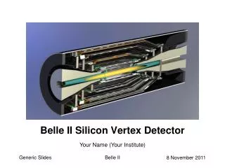
20 cm 50 cm Silicon vertex detector
basic SVD unit: Double Sided Strip Detector (DSSD) separate measurement of r and z coordinate pitch strip pitch: 50 and 75 m for r and z coordinate, respectively Evaluate the performance of SVD – measure its intrinsic resolution: Incident angle dependence, occupancy study, alignment cross-check
SVD intrinsic resolution • Error on the track position measurement • Track position is determined from the SVD hits on other layers residual DSSD SVD hit track
Typical residual distributions r coordinate z coordinate • Intrinsic resolution is determined from the width of the residual distribution: • i = 10 m, RMS = 12-15 m for r and • i = 25 m, RMS = 30 m for z coordinate residual [cm] residual [cm]
y track x x strips Incident angle dependence • Simple estimate for the perpendicular tracks: signal collected by single strip → resolution ≈ strip pitch / 12 • Small incident angle: signal collected by few strips → resolution improved • Large incident angle: signal collected by many strips → resolution gets worse due to smaller signal to noise ratio angle
Incident angle dependence: result r coordinate z coordinate RMS [m] RMS [m] 30 20 10 0 60 40 20 0 -20 0 20 40 -20 0 20 40 60 Incident angle [degrees] Incident angle [degrees] Innermost layer
Incident angle dependence: result r coordinate z coordinate RMS [m] RMS [m] 30 20 10 0 60 40 20 0 -20 0 20 40 -20 0 20 40 60 Incident angle [degrees] Incident angle [degrees] Different colors show the result for all four layers: black, red, green and blue for the innermost, second, third and outermost layer.
Distribution of hits with cluster size 1 strip,2 strips, 3 strips, … -20 0 20 40 -12o incident angle [o] Magnetic Field Effect • Intrinsic resolution is not symmetric with respect to perpendicular incident angle • Reason: magnetic field, confirmed by the plot of hit cluster size • next SVD:
n side e- direction B . Fe y E Fm p side x track track angle n side + + B . y + + E + + Fm Fm p side x Magnetic field effect • Positive angle: bigger cluster size • Negative angle: smaller cluster size
occupancy < 0.04 residual occupancy 0.3 residual Degradation of SVD intrinsic resolution due to higher detector occupancy (background): cluster distortion or cluster mis-association? Number of clusters with MC hit (correctly associated) Number of clusters with rel. change in E > 0.2 Number of clusters with MC hit (correctly associated) wrong cluster association is negligible Relative fraction of SVD hits occupancy, x coordinate
r coordinate residual [cm] Alignment cross-check • Check if residual distributions for individual SVD units are shifted (mis-aligned) • Try to correct the shift
Conclusions on the SVD intrinsic resolution study • Best resolution (RMS) at small track incident angle is found to be 12and 30 m for r and z coordinate, respectively. • Results of this study provided important information for • cross-check of the SVD alignment • different geometry design to take into account magnetic field effect • improvement of clustering algorithm in the case of higher detector occupancy
B0 fCP B0 fCP B0 B0 Analysis of data collected at the Belle detector: Measurement of Time Dependent CP Violation in B0→ D+D- Decays
c c d d t Vtb* Vtd d b W - W + b d Vtb* t Vtd B0 → D+D-CP eigenstate D- D+ B0 tree c B0 • B 0 and B0 mixes with each other • via “box-diagram”. • The box-diagram includes CKM complex phase. • A path from B0 to fCP via mixing has different weak phase from one from B0 to fCP directly due to the CKM phase. penguin c
Time-dependent decay amplitude • PCP±(t) = exp(-|t| / ) / (4) · (1±(1-2w)(S sin(mt)- C cos(mt))) • S = - sin(2) (if only tree diagrams are present) CKM triangle
Analysisfinal step: fit S and C to t distribution • Reconstruct the events • Measure the time of B meson decay from the reconstructed B vertices. • Determine B0 flavor • Properly fit the t distribution (taking into account detector resolution, mis-tagging of B mesons,…)
Brec e-: 8.0 GeV e+: 3.5 GeV e- e+ fCP (fKS) Y(4S) ~ 0.425 Dzc tB ~ 200 mm Basc Flavor tag Dz • 5 steps toward the CP asymmetry measurement • Reconstruct BfKS decays • Measure proper-time difference: Dt • Determine flavor of Basc • Evaluate asymmetry from the obtained Dt distributions • Discuss observed CP asymmetry
Event reconstruction • Br ~ 1.7 10-4 • D mesons are reconstructed only in decays to charged particles (10%) • Detector efficiency for reconstructing such an event ~ 10 – 20 % (at S/B ~ 1) Expect only few (2-3) events per 10 M BB events! High luminosity B-factory is needed – KEK! Approx. 350 M recorded BB events – about 100 of them will be correctly reconstructed as B0 → D+D-
B0 decay time • Average distance between the two decay vertices is 200 μm • Need to measure the vertex position with better accuracy • With SVD we are able to measure the vertex z coordinate with accuracy about 100 μm
t =tasc t =trec Brec = B 0 B 0-B 0 mixing Brec ??? D+D- decay ¡(4S) Basc Brec = B 0 decay(flavor-specific) Flavor tagging t Use flavor-specific decays ( slow, K, leptons)
Current status • Event selection is optimised according to best signal to background ratio. • Vertex position and tagging are determined using standard Belle software • Fitting procedure is under development (I can not show any preliminary results)
It is great to work for RICH SVD Study of CP violation Conclusion…