Download
1 / 100
1.07k likes | 1.43k Vues
Wall Insulation and Whole Building Energy Performance. John Swink, PE, LEED-AP Acme Brick Company Jswink@Brick.com 817-714-9523. Wall Insulation and Whole Building Energy Performance. Avoid disinformation about saving energy in buildings.

E N D
Wall Insulation and Whole Building Energy Performance John Swink, PE, LEED-AP Acme Brick Company Jswink@Brick.com 817-714-9523
Wall Insulation and Whole Building Energy Performance • Avoid disinformation about saving energy in buildings. • Understand real thermal performance of wall systems • Demystify whole building energy analysis.
Learning Objectives • Learn the TRUE U and R values of many common wall systems. • Learn how to calculate true U and R values for complex building envelope components. • Learn how eQuest and Simergy can help you design high performance buildings to meet sustainable goals. • Learn to integrate economical building envelopes with high performance mechanical systems for the most cost-effective energy performance.
1. True U and R Values in Building Walls Introduction – The LEED® Mandate Rising energy costs and concern for the environment have led many groups, including AIA, ASHRAE, USGBC and ICC to support much higher expectations for building energy performance. There have been many predictions and endeavors to build zero-energy and near-zero energy buildings. But there are practical limits on building performance. Today we will look at the entire building envelope to optimize the wall systems, including opaque and glazed areas, to see what those limits are, and how best to design buildings for optimum performance and value.
1. True U and R Values in Building Walls Introduction – The LEED® Mandate Traditionally, heating and cooling of buildings has been the purview of mechanical engineers on the design team. But choices made by architects and structural engineers have a significant impact on the energy performance of our buildings. So we need to understand as fully as possible how those choices can help or hurt the building’s overall energy performance. Today we will investigate the impact of various types of building envelope construction on the performance of those buildings.
1. True U and R Values in Building Walls Introduction – The LEED® Mandate – ever-decreasing energy demand for buildings. • We examine popular wall systems for ACTUAL heat flow • All include air and moisture barriers • Alternates for glazing area considered. • Mass not included in calculations, but will benefit • eQUEST or Simergy lets you quickly study the effects of different wall systems on whole building energy performance. Occupancy types are critical for effective evaluation of building performance. Energy demands vary widely:
Session Outline • Dispel some popular myths about R values • Compare popular wall systems • Detailed look at wall system heat flow • ORNL study of mass walls in a model house • Proposed mass house for optimum energy performance • School energy performance study at University of Louisville
Those “R” Lies “Oh, what a tangle web we weave when first we practice to deceive!” Sir Walter Scott Let’s look and some misinformation– or is it disinformation? – that is commonly reported. • Misinformation – erroneous information that is passed on through ignorance. • Disinformation – deliberate lies or distortions used to promote one’s cause or agenda.
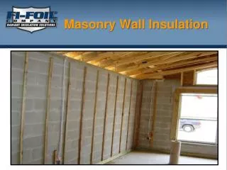
OXYMORON – “TRUE” R VALUE • Fiberglass industry only reports R value of batt insulation that is: • Perfectly placed • No studs, fasteners, wiring, etc. • No stapled facings • Batts must be in contact with all surfaces • Never happens in the field • FALSE R values reported • True R values MUCH lower
OXYMORON – “TRUE” R VALUE • Wood industry reports R value of batts, not the wall assembly. • Does not include heat flow through studs • Ignores air gaps from imperfect placement. • Stapled facings leave gaps • Wiring leaves gaps • False R values reported • True R values MUCH lower
MASONRY – TRUE R VALUE • NCMA • Calculates or tests true R value of wall assembly • Only reports True R values • Notes the effects of mass in reducing heat flow, but only as recognized by ASHRAE and supported by analysis.
Those “R” Lies Lie #1 – ICF walls have an R value of 50 • Some say “Equivalent R Value of 50.” • Equivalent to what? Truth – Typical ICF walls are R16 to R20
Those “R” Lies Lie #2 – 6” Steel stud walls are R 19 • Steel stud conducts much heat through the wall • R19 batts are only R19 if perfectly placed with no gaps Truth – 6” steel stud walls have typical R 7.03 according to AHSRAE 90.1
Those “R” Lies Lie #3 – 6” Wood stud walls are R19 • Wood studs conduct less heat than metal studs • Wood studs conduct more heat than insulation • R19 batts are only R19 if perfectly placed with no gaps Truth – typical 5.25” wood stud walls are R11.4 or less
Those “R” Lies Lie #4 – 4” Wood stud walls are R13 • Wood studs conduct more heat through the wall than insulation • R13 batts are only R13 if perfectly placed with no gaps Truth – perfectly built 3.5” wood stud walls actually R 8.4. Truth – many 3.5” wood stud walls R5 or less
Detailed Look at Wall Systems • Now let’s look at these wall systems in more detail and calculate their actual R value using the ASHRAE series-parallel method: • When DIFFERENT wall components are in the SAME LAYER, we add the heat flows (U values) for each component in that layer. (PARALLEL) • Accounts for thermal bridging that bypasses insulation. • R for that layer = 1/(Sum of U values) • When wall components are in SEPARATE LAYERS, simply ADD the R values. (SERIES) • Here are examples of walls designed for true R19
A. True U and R Values in Building Walls In this session we will compare each of the following wall systems. Each has peculiar advantages that can make them appropriate choices, but it is important to understand their limitations. • Wood Stud Walls • Steel Stud Walls • Insulated Concrete Form Walls • Tilt-up Concrete Walls • Single-Wythe Masonry Walls • Masonry Cavity Walls
1. Wall Model – 4” Wood Studs Calculate actual R valueSeries/parallel method R 3.5 – wood stud U 0.286 x 15% = 0.043 R 13.0 – batt R 9.1 reduced 30% for imperfect fill U 0.109 x 85% = 0.093 U Total = 0.043 + 0.093 = 0.136 R = 7.33 average stud cavity R = 1.11 2x 0.625” gyp board R = 8.4 average opaque wall
1. Wall Model – 4” Wood Studs Calculate actual R valueSeries/parallel method R 3.5 – wood stud U 0.286 x 15% = 0.043 R 12.6 – spray foam, sprayed cellulose, or aminoplast foam filled U 0.079 x 85% = 0.0675 U Total = 0.043 + 0.0675 = 0.111 R = 9.05 studs and insulation layer R = 1.11 2x 0.625” gyp board R = 10.2 total when stud cavities are filled with insulation, no gaps
1. Wall Model – 4” Wood Studs Calculate actual R valueSeries/parallel method R 3.5 – wood stud U 0.286 x 15% = 0.043 R 16 –aminoplast foam filled U 0.063 x 85% = 0.053 U Total = 0.043 + 0.053 = 0.96 R = 10.4 studs and insulation layer R = 1.11 2x 0.625” gyp board layer R = 11.5 total when stud cavities are filled with insulation, no gaps
1. Wall– 6” Wood StudsCalculate actual R valueSeries/parallel method R 5.5 – wood stud U 0.286 x 15% = 0.027 R 17.4 – compressed R 19 batt R 12.2 reduced 30% for imperfect fill U 0.085 x 85% = 0.070 U Total = 0.027 + 0.070 = 0.097 R = 10.3 average stud cavity R = 1.11 2x 0.625” gyp board R = 11.4 average opaque wall
1. R19 Wall – 4” Wood Studs R 0.17 – outside air boundary layer R 0.33 – Masonry veneer R 1.0 – Air space R 10.0 – 2” XPS insulation R 8.4 – Wood Studs with R 13 batts* R 0.68 – inside air boundary layer R 20.6 – Total 10.4 inches total wall thickness
1. R19 Wall – 6” Wood Studs R 0.17 – outside air boundary layer R 0.3 – Masonry veneer R 1.0 – Air space R 5.0 – 1” XPS insulation R 10.3 – Wood Studs with R 19 batts* R 0.68 – inside air boundary layer R 19.5 – Total 11.9 inches total wall thickness
2. R19 Wall– 6” Steel Studs R 0.17 – outside air boundary layer R 0.3 – Masonry veneer R 1.0 – Air space R 10.0 – Continuous insulation R 7.03 – Steel studs with R 19 batt (ASHRAE Handbook of Fundamentals) R 0.68 – inside air boundary layer R 19.1 – Total 12.9 inches total wall thickness
3. R19 Wall– Insulated Concrete Form R 0.17 – outside air boundary layer a R 0.3 – 3” Masonry veneer R 1.0 – 1” Air space R 9.5 – 2.5” EPS insulation form R 0.48 – Concrete pour R 7.5 – 2.5” EPS insulation form reduced by electrical cut-outs R 0.4 – ½” gyp board R 0.68 – inside air boundary layer R 19.4 – Total 15.3 inches total wall thickness
4. R19 Wall – 6” Tilt-up Concrete R 0.17 – outside air boundary layer R 0.5 – 6” Tilt-up Concrete Negative side dampproof coating R 10.0 – Continuous insulation (Seldom used – R10.3 without ci) R 9.0 – 6”x25ga Steel studs, R 19 batts (ASHRAE Handbook of Fundamentals) R 0.68 – inside air boundary layer R 20.3 – Total 15.6 inches total wall thickness
4. R19 Tilt-up Concrete Sandwich Panel R 0.17 – outside air boundary layer R 0.2 – 2” Concrete R 14.0 – Continuous insulation 2” polyisocyanurate R 0.5 – 6” Concrete R 0.68 – inside air boundary layer R 15.6 – Total 10.0 inches total wall thickness
5. Wall Model – Single-wythe CMU R 0.17 – outside air boundary layer R 5.7 – Core insulated CMU with grouted cells at 32” minimum and bond beams at 48” min spacing (per IECC prescriptive tables) R 0.68 – inside air boundary layer R 6.55 – Total 7.63 inches total wall thickness
6. R19 Masonry Cavity Walls R 0.17 – outside air boundary layer a R 0.3 – 3” Masonry veneer R 2.5 – Foil-faced 1” air space R 14 – 2” foil-faced polyiso board R 2 – 6” CMU uninsulated R 0.68 – inside air boundary layer R 19.5 – Total 11.3” inches total wall thickness
6. Wall Model – Masonry Cavity Walls R 0.17 – outside air boundary layer a R 0.30 – Masonry veneer R 2.5 – Foil-faced 1” air space R 10.5 – 1.5” foil-faced polyiso board R 5.7 – 8” CMU grouted 48” c/c R 0.68 – inside air boundary layer R 19.9 – Total 12.8 inches total wall thickness
True Mass Effect • Many wall systems, including masonry, tilt-up, and ICF’s claim a benefit from mass in the wall system to improve energy performance. • Computer simulations at ORNL show where mass should be placed for maximum benefit. • This debunks claims of some wall systems to benefit from mass.
Oak Ridge National Laboratory Study • This recent study at ORNL found significant improvement in energy performance of a 1500 sf house with properly placed mass elements in the walls.
HDD / CDD 3” Conc 3” Conc 4” Conc 2” Conc 6” Conc 6” Conc 6” Conc 6” Conc 4” EPS 4” EPS 4” EPS 4” EPS 1” EPS 3” EPS 2” EPS 2” EPS WALL 1 WALL 2 WALL 3 WALL 4 WALL 5 WALL 6 MASS INSIDE INSULATION OUTSIDE MASS BURIED IN INSULATION (ICF) MASS NOT EFFECTIVE MASS OUTSIDE INSULATION INSIDE (TILT-UP WITH INSIDE INSULATION) MASS NOT EFFECTIVE
ORNL Study – Energy Use in Houseshttp://www.ornl.org/sci/roofs+walls/staff/papers/Effect%20of%20Insulation%20and%20Mass%20Distribution.pdf
Similar to Masonry Cavity Wall ICF Wall Cavity Wall Savings Cavity Wall Savings Cavity Wall Savings Savings on heat flow through wall only (estimated)
What does this mean? • This study shows significant savings for walls with mass exposed to inside air compared with mass isolated within insulation. • Walls account for only 25% of the heat loss for these houses. • If we divide total savings in heat load by 25%, we can see that walls with mass exposed to inside air reduce heat loss through walls by up to 34% in Phoenix and 30% in Atlanta. • DFW savings would be in this 30% range as well.
Limitations on the ORNL study. • Significant wall types were not studied: • Masonry veneer over steel studs • Masonry veneer over wood studs • Whole building energy modeling does not show heat losses in walls directly
NBS 45 Study July 1973 • Computer models • Full scale testing • Showed mass benefits • Stabilized indoor temperatures • Reduced heating and cooling loads • +/- 0.8° F indoors • +- 27.5° F outdoors
Proposed Mass House in DFW Using the adobe effect in DFW, a mass house could greatly reduce energy consumption by storing several days’ heat flow to take advantage of outside temperature variations and eliminate mechanical heating and cooling. • Walls would be solid masonry or concrete to maximize mass. • Ground floor would be slab-on-grade with perimeter insulation to maximize heat storage in the slab and the soil under it with ground temperature at 68ᵒF. • Attic floor would be 8” solid concrete. • Total mass for 1500 sf house would be 600,000 lbm • At 0.22 sp heat it takes 132,000 btu to raise the temperature one degree F. • In 18 hours of 90 deg weather, temperature will rise 3 deg F
2011 Daily High and Low Temperatures, DFW Airport Daily Highs Daily Lows Jan Feb Mar Apr May Jun Jul Aug Sep Oct Nov Dec Thermostat Set-points 68ᵒF to 75ᵒF Solar Heating Ventilation Only No Heat or AC Efficient Air Conditioning Ventilation Only No Heat or AC Solar Heating
Proposed Mass House in DFW • Daily high and low temperatures in the DFW area shows approximately 6 months when outside temperatures fall within the comfort zone as defined by thermostat set points. During these times, outside air could be brought in to either heat or cool indoor air at appropriate times of the day. • Light-framed houses will require supplemental heating and cooling during these times, because they can only store sufficient heat to maintain temperatures for several hours.