Download

1 / 33
340 likes | 574 Vues
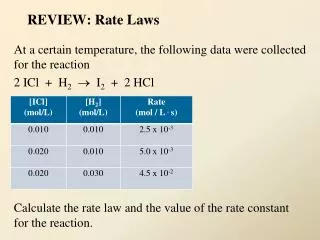
Review: Kirchhoff’s Laws and Resistive Circuits. Review Kirchhoff’s Laws. Kirchhoff’s Current Law (KCL): Sum of currents at each supernode is zero. Review Kirchhoff’s Laws. Kirchhoff’s Voltage Law (KVL): Sum of voltages at each loop is zero. Circuit elements. Circuit elements.

E N D
Review Kirchhoff’s Laws • Kirchhoff’s Current Law (KCL): • Sum of currents at each supernode is zero
Review Kirchhoff’s Laws • Kirchhoff’s Voltage Law (KVL): • Sum of voltages at each loop is zero
Resistive circuits • To analyze a circuit write KCL equations in all super nodes except one • Use voltage information and controlled source gains
Exercise resistive circuits Find nodal voltages in this circuit
Exercise resistive circuits Find nodal voltages in this circuit
Two- terminal circuit Two- terminal circuit A in B Finding Thevenin equivalent • Three step process: • Find voltage on open terminals A-B • Find current on shorted terminals A-B A + Vt _ B
Rt + Vt _ Finding Thevenin equivalent • Three step process: • 3. Find Equivalent resistance • Rt=Vt/in A + _ B
A + Vt _ B Thevenin equivalent circuit Step 1. Find Vt
Thevenin equivalent circuit • Step 3. Find Equivalent resistance • Rt=Vt/isc Step 2. Find isc
Exercise Thevenin equivalent Step 1. Find Vt
Exercise Thevenin equivalent • Step 3. Find Equivalent resistance • Rt=Vt/isc Step 2. Find isc
Figure D.1 Multisim results for a simple dc circuit
Memristance a new element The four circuit quantities (charge, current, voltage, and magnetic flux) can be related to each other in six ways. Two quantities are covered by basic physical laws, and three are covered by known circuit elements (resistor, capacitor, and inductor). In 1971 Chua proposed the memristor, as a class of circuit elements based on a relationship between charge and flux.
How memristance works? • Memristor is defined as an element that relates flux and charge • Memristance value is computed as • and can be related to voltage – current relation as follows • Thus effectively it is a charge dependent resistance
Four basic passive elements Nonlinear Linear Local value Resistor R Capacitor C Inductor L M Memristor
How memristance works? 1 May 2008 Stanley Williams from HP was able to fabricate and test memristors using electrical characteristics of certain nanoscale devices. Researchers in HP think the new element could pave the way for applications both near- and far-term, from nonvolatile RAM to realistic neural networks. Early memristor circuit
Memristor design • CROSSBAR ARCHITECTURE: A memristor’s structure, shown here in a scanning tunneling microscope image, will enable dense, stable computer memories. Memristors build by Williams
Memristor based design The most obvious benefit is to memories. Because memristors remember their state, they can store data indefinitely, using energy only when you toggle or read the state of a switch, unlike the capacitors in conventional DRAM, which will lose their stored charge if the power to the chip is turned off. Furthermore, the wires and switches can be made very small: we should eventually get down to a width of around 4 nm, and then multiple crossbars could be stacked on top of each other to create a ridiculously high density of stored bits.
How memristance works? THE CROSSBAR ARCHITECTURE: • The crossbar architecture is a fully connected mesh of perpendicular wires. • Any two crossing wires are connected by a switch. • To close the switch, a positive voltage is applied across the two wires to be connected. • To open the switch, the voltage is reversed.
How memristance works? THE SWITCH: • A switch is a 40-nanometer cube of titanium dioxide (TiO2) in two layers: • The lower TiO2 layer has a perfect 2:1 oxygen-to-titanium ratio, making it an insulator. • By contrast, the upper TiO2 layer is missing 0.5 percent of its oxygen (TiO2-x). • The vacancies make the TiO2-x material metallic and conductive.
How memristance works? APPLIED MEMRISTANCE: • The oxygen deficiencies in the TiO2-x manifest as “bubbles” of oxygen vacancies scattered throughout the upper layer. • A positive voltage on the switch repels the (positive) oxygen deficiencies in the metallic upper TiO2-x layer, sending them into the insulating TiO2 layer below. • That causes the boundary between the two materials to move down, increasing the percentage of conducting TiO2-x and thus the conductivity of the entire switch. • The more positive voltage is applied, the more conductive the cube becomes.
How memristance works? • A negative voltage on the switch attracts the positively charged oxygen bubbles, pulling them out of the TiO2. • The amount of insulating TiO2 increases, making the switch more resistive. • The more negative voltage is applied, the less conductive the cube becomes. • When the voltage is turned off, the oxygen bubbles do not migrate. • They stay where they are, which means that the boundary between the two titanium dioxide layers is frozen. • That is how the memristor “remembers” how much voltage was last applied.
How memristance works? • Leon Chua’s original graph of the hypothetical memristor’s behavior is shown at top right; • The graph of R. Stanley Williams’s experimental results in the Nature paper is shown below. • The loops map the switching behavior of the device: • It begins with a high resistance, and as the voltage increases, the current slowly increases. • As charge flows through the device, the resistance drops, • Then, as the voltage decreases, the current decreases but more slowly, because charge is flowing through the device and the resistance is still dropping. • The result is an on-switching loop. • When the voltage turns negative, the resistance of the device increases, resulting in an off-switching loop.
How to implement analog weights in NN? THINKING MACHINE?: • This artist’s conception of a memristor shows a stack of multiple crossbar arrays. • Because memristors behave functionally like synapses, using memristors could lead to analog circuits that can simulate synaptic connections in neural networks.