Download
1 / 61
860 likes | 1.3k Vues
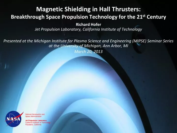
Magnetic Shielding in Hall Thrusters: Breakthrough Space Propulsion Technology for the 21 st Century. Richard Hofer Jet Propulsion Laboratory, California Institute of Technology

E N D
Magnetic Shielding in Hall Thrusters: Breakthrough Space Propulsion Technology for the 21st Century Richard HoferJet Propulsion Laboratory, California Institute of Technology Presented at the Michigan Institute for Plasma Science and Engineering (MIPSE) Seminar Series at the University of Michigan, Ann Arbor, MI March 20, 2013 National Aeronautics and Space Administration Jet Propulsion Laboratory California Institute of Technology Pasadena, California
Acknowledgements • The research described here is the result of a multi-year investigation of magnetic shielding in Hall thrusters conducted by the Electric Propulsion group at JPL. • Modeling: Ioannis Mikellides, Ira Katz • Experiments: Dan Goebel, Jay Polk, Ben Jorns • The research described here was carried out at the Jet Propulsion Laboratory, California Institute of Technology, under a contract with the National Aeronautics and Space Administration. Program sponsorship includes: • JPL R&TD program • JPL Spontaneous Concept program • NASA In-Space Propulsion project in the Space Technology Mission Directorate (STMD)
Asteroid Retrieval Mission KISS Study Concept About the same mass as the International Space Station 6.5-m dia. 340-t “Levitated Mass” at the LA County Museum of Art 40-kW SEP is enabling Brophy, J. and Oleson, S., "Spacecraft Conceptual Design for Returning Entire near-Earth Asteroids," AIAA-2012-4067, July 2012.
Historical Perspective Electric Propulsion Missions
Uses for Electric Propulsion High ΔV space missions Low-disturbance station keeping High precision spacecraft control
Hall Thruster Operation • Electrons from the cathode are trapped in an azimuthal drift by the applied electric (E) and magnetic fields (B). • Neutral propellant gas is ionized by electron bombardment. • Ions are accelerated by the electric field producing thrust. • Electrons from the cathode neutralize the ion beam.
Conceptual Framework Br Ez Distribution of E & B along the channel (Kim, JPP 1998) Magnetic field lines Hall thrusters use an axial electric field and a radial magnetic field to accelerate ions and confine electrons. The magnetic field intensity is sufficient to magnetize electrons while the cross-field configuration induces an azimuthal electron drift in the ExB direction. These conditions severely restrict the axial electron mobility allowing for efficient ionization of the neutral propellant and the establishment of the self-consistent electric field, which must sharply rise in the region of maximum magnetic field intensity in order to maintain current continuity. Due to their much greater mass, ions are unimpeded by the magnetic field but are accelerated by the electric field to produce thrust.
Fundamental properties of the Hall thruster discharge Isothermality ϕ “Thermalized Potential” Te ne • Along field lines electrons stream freely • and the electric field is balanced by the electron pressure • The transverse B and ExB configuration implies a high Hall parameter • with the cross-field mobility reduced by ~1/Ω2
Experimental evidence demonstrating the isothermality of lines of force Outer wall probe locations Measured magnetic field lines Inner wall probe locations AIAA-2012-3789
Two big problems in Hall thruster research have remained unresolved for over 50 years Advanced magnetic field topologies vastly improved the performance at high-Isp. Hofer, R. R. and Gallimore, A. D., "High-Specific Impulse Hall Thrusters, Part 1: Influence of Current Density and Magnetic Field," Journal of Propulsion and Power 22, 4, 721-731 (2006). • Cross-field e- mobility limiting performance • Still don’t understand, but we can measure it and model it in an ad hoc fashion • Developed design strategies to regulate the electron current and achieve high-performance • Discharge chamber erosion limiting life • Magnetic shielding essentially eliminates the primary failure mode
H6 Hall ThrusterWorld’s Most Efficient Xenon Hall Thruster • The H6 is a 6 kW Hall thruster designed in collaboration with AFRL and the University of Michigan • The thruster was designed to serve as a high-performance test bed for fundamental studies of thruster physics and technology innovations • High-performance is achieved through advanced magnetics, a centrally-mounted LaB6 cathode, and a high uniformity gas distributor • Throttleable from 2-12 kW, 1000-3000 s, 100-500 mN • At 6 kW, 300 V (unshielded): 0.41 N thrust, 1970 s total Isp, 65% total efficiency • At 6 kW, 800 V (unshielded): 0.27 N thrust, 3170 s total Isp, 70% total efficiency • Highest total efficiency of a xenon Hall thruster ever measured. H6 LaB6 Hollow Cathode
Performance has improved by ~40% since 1998 H6 (2006) Hofer, Brown, Reid, Gallimore P5 (1998) Haas, Gulczinski, Gallimore NASA-173Mv2 (2003) Hofer, Gallimore NASA-173Mv1 (2001) Hofer, Peterson, Gallimore
Thruster life has been the major technology challenge in electric propulsion since 1959 • Thruster life is a fundamental constraint on mission performance affecting • ΔV capability • NASA’s Dawn spacecraft carries 2 prime + 1 redundant thruster strings in order to meet the mission requirements. • Spacecraft dry mass • Cost • Reliability
Discharge chamber erosion from high-energy ion impact is the primary life limiting failure mode in (unshielded) Hall thrusters RedepositionZone ErosionZone AIAA-2005-4243 Volumetric Wear Rate (Arb) Volumetric erosion rate decreases with time as the ion incidence angle becomes increasingly shallow. In traditional (unshielded) Hall thrusters, the erosion rate never decreases enough to avoid failure. Time (h) As a fundamental constraint on mission performance, thruster life has been the major technology challenge in electric propulsion since 1959. In Hall thrusters, high-energy ions sputter erode the ceramic walls of the discharge chamber, eventually exposing the magnetic circuit and leading to thruster failure. The erosion rate decreases with time as the walls recess causing the angle of the ions with respect to the wall to become increasingly shallow. However, the erosion never stops and eventually the walls erode away and expose the magnetic circuit. Until recently, thruster lifetime has always been the major hurdle towards widespread adoption of Hall thrusters on deep-space missions
Magnetic Shielding in Hall Thrusters Isothermal field lines Thermalized potential Mikellides, I. G., Katz, I., Hofer, R. R., and Goebel, D. M., "Magnetic Shielding of Walls from the Unmagnetized Ion Beam in a Hall Thruster," Applied Physics Letters 102, 2, 023509 (2013). • What does it do? It eliminates channel erosion as a failure mode by achieving adjacent to channel surfaces: • high plasma potential • low electron temperature • How does it do it? It exploits the isothermality of magnetic field lines that extend deep into the acceleration channel, which marginalizes the effect of Te×ln(ne) in the thermalized potential. • Why does it work? It reduces significantly ALL contributions to erosion: ion kinetic energy, sheath energy and particle flux. • Status? Peer-reviewed, physics-based modeling and laboratory experiments have demonstrated at least 100X reductions in erosion rate.
Physics-based design methodology utilized to modify the H6 in order to achieve magnetic shielding Mikellides, I. G., Katz, I., Hofer, R. R., and Goebel, D. M., "Design of a Laboratory Hall Thruster with Magnetically Shielded Channel Walls, Phase III: Comparison of Theory with Experiment," AIAA-2012-3789, July 2012. • Design modifications achieved through virtual prototyping • JPL’s Hall2De used to simulate the plasma and erosion • Infolytica’s Magnet 7 used to design magnetic circuit • Goal was to achieve magnetic shielding while maintaining high performance
Experimental Apparatus • H6 Hall thruster • Owens Chamber at JPL • 3 m diameter X 10 m long • Graphite lined • P ≤ 1.6x10⁻⁵ Torr • Sixteen diagnostics for assessing performance, stability, thermal, and wear characteristics • Thrust stand • Current probes for measuring discharge current oscillations • Thermocouples & thermal camera • Far-field ExB, RPA, & emissive probes • Near-field ion current density probe • High-speed discharge chamber Langmuir and emissive probes (φ,Te) • Flush-mounted wall probes (φ,Te, ji) • Coordinate measuring machine (CMM) for wall profiles • Quartz Crystal Microbalance (QCM) for measuring carbon backsputter rate • Residual Gas Analyzer (RGA) • 3-axis Gaussmeter • Digital camera
Visual observations provide qualitative evidence of reduced plasma-wall interactions US MS MS Anode is visible when viewedalong the wall. Distinct differences in the structure of the plasma in the discharge chamber were observed. These qualitative observations, were our first indication that plasma-wall interactions were reduced and magnetic shielding had been achieved.
High-performance maintained in the magnetically shielded configuration • Stability: Discharge current oscillation amplitude increased 25%. Global stability of the discharge maintained • Thermal: Ring temperatures decreased 60-80 °C (12-16%). • US: 401 mN, 1950 s, 63.5% • MS: 384 mN (-4.2%), 2000 s (+2.6%), 62.4% (-1.7%) • Efficiency analysis shows: • Thrust decreased due to higher plume divergence angle (+5°) • Isp increased due to higher fraction of multiply-charged ions (Xe+ decreased from 76% to 58%)
Stable operation maintained in the magnetically shielded configuration Discharge current oscillation amplitude increased 25% Global stability of the discharge maintained 80 kHz modes observed, possibly linked to cathode oscillations
Decreased insulator ring temperatures measured with the magnetically shielded configuration Thermal camera imagery Thermal characteristics essentially unchanged and may have been improved as indicated by a 60-80 °C (12-16%) decrease in insulator ring temperatures.
Plasma conditions measured at the wall are consistent with the predictions of magnetic shielding theory In the MS configuration, plasma potential was maintained very near the anode potential, the electron temperature was reduced by 2-3X, and the ion current density was reduced by at least 2X.
After MS testing, insulator rings mostly covered in carbon deposits MS Before Testing MS After Testing QCM measured carbon backsputter rate of 0.004 μm/h (~2000X less than US erosion rates) Second qualitative observation that magnetic shielding had been achieved.
Inner insulator rings from the various trials US magnetic circuit with MS wall geometry Wall chamfering was NOT the sole cause of the MS case erosion rate reduction
Wall erosion in Hall thrusters Xe+ Boron nitride wall Potential BN Pre-Sheath/Bulk Plasma Sheath Erosion of the boron nitride walls in Hall thrusters is due to high-energy ion bombardment Ions gain energy through potential drops in the bulk plasma and through the wall sheath
Carbon deposition and erosion rates O(1-10) over 50-200 eV Carbon backsputter rate “Undisturbed” erosion rate Xe+ BN C C BN (w/ C) Interpretation of carbon deposits complicated by uncertainty in the sputter yields of carbon and BN under low-energy Xe impact BN and C thresholds are in the range of 25-50 eV. The maximum ion energy for the MS case was 36 eV. If YBN/YC is O(1-10) near threshold, erosion rate was less than or equal to 0.004 – 0.08 μm/h, a reduction of 100-2000X from the US case.
Coordinate Measuring Machine (CMM) Erosion Rates 8.5 μm/h US case Net deposition MS case US rates are typical of Hall thrusters at beginning-of-life (BOL). MS rates are below the noise threshold of the CMM.
Wall erosion rates reduced by 1000X as computed from directly measured plasma properties at the wall 1000X (min) Uncertainty dominated by the ion current density (50%) and sputter yield (30%), resulting in a combined standard uncertainty of 60%. Within this uncertainty, US erosion rates are consistent with the CMM data. For MS case, ion energy is below 30.5 eV threshold (Rubin, 2009) for all but two locations on the inner wall where 10-13 eV electron temperatures were measured. Still, the MS erosion rates are at least 1000X below the US case. Erosion rates calculated this way are independent of facility effects!
2D numerical simulation results Mikellides, I. G., Katz, I., Hofer, R. R., and Goebel, D. M., "Magnetic Shielding of Walls from the Unmagnetized Ion Beam in a Hall Thruster," Applied Physics Letters 102, 2, 023509 (2013).
Various rates encountered in these experiments and other relevant cases
Throughput range achievable with magnetically shielded Hall thrusters H6MS: from erosion rate measurements scaled relative to lower SPT-100 limit of 30 kg/kW. NEXT: 113 kg/kW demonstrated to date. 141 kg/kW estimated. NSTAR: 102 kg/kW demonstrated. BPT-4000: 100 kg/kW demonstrated. 400 kg/kW estimated by vendor. SPT-100: poles exposed at 30 kg/kW. 93 kg/kW demonstrated. • Throughput capability of magnetically shielded Hall thrusters is literally off the charts • Possible cathode limitations can be addressed with redundant cathodes • Only magnetically shielded Hall thrusters have the throughput capability to meet the most demanding deep-space missions without flying extra strings
Summary of MS Investigations at 2000 s Isp Collectively, these changes effectively eliminate wall erosion as a life limitation or failure mode in Hall thrusters, allowing for new space exploration missions that could not be undertaken in the past. In a controlled A/B comparison, sixteen diagnostics were deployed to assess the performance, thermal, stability, and wear characteristics of the thruster in its original and modified configurations. Practically erosion-free operation has been achieved for the first time in a high-performance Hall thruster Plasma measurements at the walls validate our understanding of magnetic shielding as derived from the theory. The plasma potential was maintained very near the anode potential, the electron temperature was reduced by a factor of 2 to 3, and the ion current density was reduced by at least a factor of 2. Measurements of the carbon backsputter rate, wall geometry, and direct measurement of plasma properties at the wall indicate the wall erosion rate was reduced by 1000X relative to the unshielded thruster and by 100X relative to unshielded Hall thrusters late in life.
Magnetic Shielding Investigations H6C • 2010-2011 program established the first principles of magnetic shielding through a rigorous program of physics-based modeling and detailed laboratory experiments • Mikellides, I. G., Katz, I., Hofer, R. R., and Goebel, D. M., "Magnetic Shielding of Walls from the Unmagnetized Ion Beam in a Hall Thruster," Applied Physics Letters 102, 2, 023509 (2013). • Success of this program implied substantial growth capability for this technology to advanced Hall thruster designs • Metallic wall thrusters – demonstrated late 2011. Patent pending. • High-power thrusters – NASA-300MS re-design (in progress) • High-voltage thrusters – 2012-2013 • High-power density
H6MS experiments implied significantly reduced plasma-wall interactions. Is the wall material still important? An extensive set of modeling and experiments have shown that magnetic shielding radically reduces plasma-wall interactions If the plasma is not interacting with the walls, then why make them out of boron nitride? Boron nitride was originally chosen for low secondary electron yield and low sputtering yield If these are negligible, then why bother with BN? We obtained funding from JPL R&TD to investigate other wall materials Selected graphite for the first demonstration Simple, lightweight, strong, easy to make, ….. Alternative materials will likely also work, provided the material can tolerate wall temperatures 400-600 C.
Carbon Wall Thruster (H6C) The Black Edition
H6C Operation Looks identical to the H6MS - plasma is still off the walls
H6C Performance Performance within 1-2% of BN wall results Rings float at 5-10 V below the anode potential Stable operation identical to the H6MS with BN rings observed
Reduction in wall temperature observed due to emissivity increase with graphite and a lower deposited power
H6C Implications Elimination of the boron nitride rings has many advantages for existing Hall thrusters Lower cost Simpler thruster fabrication….especially for large high power thrusters Easier structural design for vibe/launch loads This innovation could lead to higher power densities Thruster power level likely now limited by anode dissipation (radiation) Entire channel can now be made of a single piece of material at anode potential (large radiator) Anticipate factor of 2 to 3 times higher power in a given thruster size Same 5 kW thruster today turns into a 10-15 kW thruster when needed New thruster designs and capabilities need to be explored
Pathfinding studies of high-voltage operation demonstrated discharge stability, performance, and thermal Studies conducted in 2012 at JPL were the first to operate a magnetically-shielded thruster at discharge voltages >400 V Demonstrated stable discharges up to 800 V, 12 kW Performance mappings demonstrated high-efficiency operation Thermal capability demonstrated over time scales of a few hours
Magnetic shielding at 3000 s Isp demonstrated after 100 h wear test MS Before Testing MS After Testing Insulator rings largely coated with backsputtered carbon after 113 h wear test at 800 V, 9 kW QCM measured carbon backsputter rate of 0.0025 μm/h Erosion rates ~100-1000X lower than unshielded Hall thrusters
The H6 Design Process(or, How Most Hall Thrusters are Designed) In 2006, the H6 design process was a combination semi-empirical design rules and physics-based design. Plasma-based solvers were not used to design for performance or life.