Download
1 / 18
190 likes | 510 Vues
Coupling ROMS and WRF using MCT. Coupling design and implementation. ROMS 2.0. ROMS 2.0 – new version changed from F77 to F90/F95 explicit interfaces subject to “strong typing” allocation is via dereferenced pointer structures

E N D
Coupling ROMS and WRF using MCT Coupling design and implementation
ROMS 2.0 • ROMS 2.0 – new version • changed from F77 to F90/F95 • explicit interfaces subject to “strong typing” • allocation is via dereferenced pointer structures • parallel framework includes shared- and distributed- memory paradigms
WRF-Weather Research and Forecasting • Designed for: • 1-10 km horizontal grid resolution • advanced data assimilation and model physics • both research and operations • performance and maintainability • Developed at: • NCAR • NOAA – NCEP/FSL/GFDL • EPA – Atmospheric Modeling Division • University Community
The Coupler • WRF and ROMS are coupled using the Model Coupling Toolkit (MCT) developed at Argonne National Labs • MCT handles the passing of variables between the ocean and atmosphere models, as well as regridding and time averaging
The Model Coupling Toolkit • Cons • Component model processing element (PE) pool sizes remain constant • Components can exchange only real and integer data as groups of vectors • Pros • Any number of components (ocean, atmos, ice, wave spray, etc) • Any decomposition • Any number of processors-per component • local re-gridding supported by sparse-matrix multiplication • The MCT user can supply: • Consistent numbering schemes for grid points • Integer ID for each component • An MPI communicator for each component • Interpolation Matrix Elements
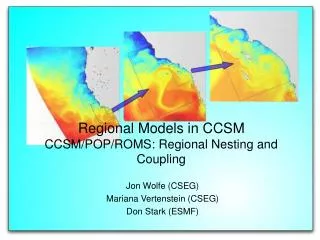
Parallel data passing Each component model in the MCT framework passes the coupler information about the decomposition of the data arrays in the form of a Global Segment Map This allows for parallel data transfer, and the ability to regrid from the atmosphere grid to the ocean on local processors. A sample decomposition, and resulting Global Segment Map is shown in the next slide.
17 17 18 18 19 19 20 20 13 13 14 14 15 15 16 16 9 9 10 10 11 11 12 12 5 5 6 6 7 7 8 8 1 1 2 2 3 3 4 4 Numbering of gridpoints GlobalSegMapExamples 2 atmosphere Pe_loc start length 0 1 8 1 9 8 2 17 4 1 Total number of segments = 3 0 Pe_loc start length 0 1 2 0 5 2 0 9 2 1 3 2 1 7 2 1 11 2 2 13 2 2 17 2 3 15 2 3 19 2 Processor Decomposition 2 3 Total number of segments = 10 ocean 0 1
Coupling through I/O API • WRF I/O API abstracted to allow changing packages (netCDF, HDF5, etc) • passing 2-D fields at the air-sea interface equivalent to file I/O • standard interface allows • easy interchange of components • easy interchange of variables passed • ROMS changes (all CPP “switches”) • new module “mod_io_couple.F” • ocean.F subroutinized – takes communicator as argument, passed to distribute.F • communicator pass to distribute.F, MPI initialization and finalization done by coupler • input file now handles tiling
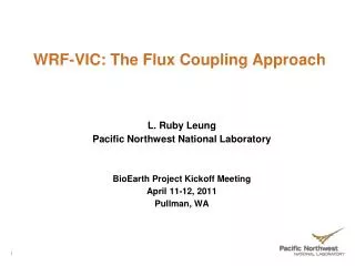
Variables Passed Atmospheric Model (WRF) SST - Sea Surface Temp t - Wind Stress Q - heat (short wave and long wave) E - Evaporation P - Precipitation QLW QSENS QLATENT t QSW E-P SST Oceanic Model (ROMS)
Alpha coupling --The first runs The initial coupling took a sample test problem from WRF that integrates the evolution of a supercell. ROMS and WRF were run on the same grid so no sparse-matrix multiplication was needed, and the fast dynamics of the 3 hour simulation meant that ROMS and WRF could be run at similar timestep sizes to eliminate the need for time averaging. ROMS was given an initial stratification typical of summertime off the Florida coast, where supercells have been observed, and was forced only by the WRF-generated surface winds
Initial Model Results Updraft cells (yellow/white) drove strong convergent surface winds (white arrows) resulting in strong (2-3 m/s) surface currents. Surface height (color slice) variations of a half-meter over 20 km were observed, and waves propagate along the thermocline (shown in blue).
Future Work • Currently only SST and Winds are passed between models - other variables need to be passed and implemented into model forcing • Allow models to run on separate grids (regridding with MCT) • Time averaging of fields using MCT accumulator needs to be implemented • Coupling across the TeraGrid (next slide)
Coupled Modeling Across the TeraGrid NCSA IA-32 Cluster (Myrinet) PSC Alpha Cluster (Quadrics) Wind Stress ROMS WRF SST In a collaborative effort between the NOAA PMEL and FSL laboratories, NCAR and Argonne, a version of the coupled WRF/ROMS model is being developed in which the ROMS component runs on one TeraGrid machine and the WRF component runs on a second TeraGrid machine. Intra-component communication occurs over, for example, Myrinet or Quadrics while inter-component communication (exchange of boundary conditions) will occur over the TeraGrid fiber-optic backbone. MPICH-G2, a globus-enabled version of MPI will provide the communication library used to implement all communication. The coupled model is divided into components using the Lawrence Berkeley Laboratory Multi-Program Component Handshaking (MPH) software. Parallel re-gridding of boundary conditions exchanged between the two models will be implemented using the Argonne Model Coupling Toolkit (MCT).
Abstract • WRF/ROMS coupling design and implementation using the Model Coupling Toolkit • Rob Jacob, Dale Haidvogel, Al Hermann, John Michalakes, Christopher Moore Dan Schaffer • WRF and ROMS are coupled using the Model Coupling Toolkit (MCT) developed at Argonne National Laboratory. MCT is a Fortran90 library built on top of MPI with data types and methods that simplify the construction of distributed-memory parallel couplers. The coupler design itself is parallel, avoiding bottlenecks by allowing for parallel exchange of fields between models on different grids, and time averaging over the coupling period. The coupling is wired into the mediation layer in WRF, and into the I/O layer in ROMS. • The initial coupling passes wind-stress from WRF to ROMS and sea surface temperature from ROMS to WRF. Longwave and shortwave heat and evaporation/precipitation will soon be added as variables passed. A simulation is run with WRF creating a supercell, and ROMS integrating the oceanic response. WRF creates the typical “hook-return” convective updraft usually seen in storms that generate supercells, as well as high precipitation and updraft-splitting. The ROMS response shows upwelling/downwelling patterns centered on the supercell updraft location, and oceanic circulation that mimics that of measured oceanic response to offshore supercell storms. • Future work includes developing an API that will allow coupling and I/O using MCT and HDF5, and utilizing this API in both WRF and ROMS, as well as coupling across the TeraGrid using MPICH-G2.
MCT Distribution Architecture { High-level MCT classes Model Coupling Toolkit Low-level MCT classes Message-Passing Environment Utilities (MPEU)

![Mechatronic Systems Design [MCT 4230/ MCT 4125/MCT 6102] Course Administrative and Introduction](https://cdn1.slideserve.com/3318098/mechatronic-systems-design-mct-4230-mct-4125-mct-6102-course-administrative-and-introduction-dt.jpg)