Download
1 / 59
590 likes | 721 Vues
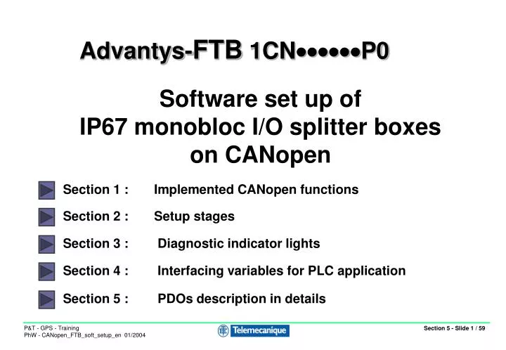
Advantys- FTB 1CN P0. Software set up of IP67 monobloc I/O splitter boxes on CANopen. Section 1 : Implemented CANopen functions. Section 2 : Setup stages. Section 3 : Diagnostic indicator lights. Section 4 : Interfacing variables for PLC application.

E N D
Advantys-FTB 1CNP0 Software set up of IP67 monobloc I/O splitter boxes on CANopen Section 1 : Implemented CANopen functions Section 2 : Setup stages Section 3 : Diagnostic indicator lights Section 4 : Interfacing variables for PLC application Section 5 : PDOs description in details
Section 1: Implemented CANopen functions - 2 Process Data Objects = PDO • CANopen IP67 I/O monobloc splitter boxes can control: • 2 predefined receive PDOs (except for module FTB1CN16EP0 16 inputs: only 1 PDO) • 2 predefined transmit PDOs • The predefined mapping can be modified to meet a specific user requirement. Supported transmission modes: • Receive: Synchronous cyclic and acyclic and asynchronous • Transmit: Synchronous cyclic and acyclic, asynchronous, and on Remote frame
Section 1: Implemented CANopen functions - 3 Predefined PDOs description • 2 predefined transmit PDOs (inputs) : • PDO 1800 = 1 to 2 bytes : Inputs states / DESINA Diagnostic • PDO 1805 = 2 to 6 bytes : Diagnostic module-channel • 2 predefined receive PDOs (outputs) : • PDO 1400 = 1 to 2 bytes Outputs command • PDO 1405 = 1 to 3 bytes Channels 1. configuration : input or DESINA diag. Channels 1. and 0. configuration : input or output (FTB1CN 16C P0 module only)
Chapitre 1 : Fonctionnalités CANopen implémentées - 4 Predefined Transmit PDOs 1800 Inputs states or DESINA diagnostic if configured. Bit 15 Bit 0 16I 6000/2 : Inputs/Diag 10 to 17 6000/1 : Inputs 00 to 07 6000/2 : Inputs/Diag 10 to 17 6000/1 : Inputs 00 to 03 12I/4O 8I/8O Reserved 6000/1 : Inputs 10 to 17 16C 6000/2 : Inputs/Diag 10 to 17 6000/1 : Inputs 00 to 07
Chapitre 1 : Fonctionnalités CANopen implémentées - 5 Predefined Transmit PDOs 1805 Diagnostic module-channels Bit 15 Bit 0 16I 3000/2 : Sensor short circuit connectors 0 to 7 3000/1 : Common diagnostic 3000/2 : Sensor short circuit connectors 0 to 7 3000/1 : Common diagnostic 12I/4O 3000/5 : Actuator warning chan. 00 to 07 3000/3 : Actuator overload chan. 00 to 07 3000/1 : Common diagnostic 3000/2 : Sensor short circuit connectors 0 to 7 8I/8O 3000/5 : Actuator warning chan. 00 to 07 3000/3 : Actuator overload chan. 00 to 07 3000/2 : Sensor short circuit connectors 0 to 7 3000/1 : Common diagnostic 3000/4 : Actuator overload chan. 10 to 17 3000/3 : Actuator overload chan. 00 to 07 16C 3000/6 : Actuator warning chan. 10 to 17 3000/5 : Actuator warning chan. 00 to 07
Chapitre 1 : Fonctionnalités CANopen implémentées - 6 Predefined Receive PDOs 1400 Outputs commands 16I PDO 1400 is not implemented on the 16 inputs module Bit 15 Bit 0 12I/4O Reserved 6200/1 : Outputs 04 to 07 8I/8O Reserved 6200/1 : Outputs 00 to 07 6200/2 : Outputs 10 to 17 6200/1 : Outputs 00 to 07 16C
Chapitre 1 : Fonctionnalités CANopen implémentées - 7 Predefined Receive PDOs 1405 Channels 1. configuration : input or DESINA diagnostic.Channels 1. and 0. configuration : input or output (FTB1CN 16C P0 only) Bit 0 Bit 15 Reserved 2000/1 : Input or Diag config. channels 10 to 17 16I 12I/4O Reserved 2000/1 : Input or Diag config. channels 10 to 17 8I/8O Reserved 2000/1 : Input or Diag config. channels 10 to 17 2001/1 : Input or output config. channels 00 to 07 2000/1 : Input or Diag config. channels 10 to 17 16C Reserved 2001/2 : Input or output config. channels 10 to 17
1 transmit SDO, 1 receive SDO Allowing access to any dictionary object by message exchange. Can be used for example to set parameters for: Input logic: NO - NC contact Output logic: NO - NC status Fallback position for outputs: Maintain/fallback to 0/fallback to 1 in the event of communication problems Operation of channel 1 (pin 2): Input or sensor with integral diagnostics These parameters can be set when the network is initialised (Object Configuration window) or by programming in the application. Section 1: Implemented CANopen functions - 8 Service Data Object = SDO
Section 1: Implemented CANopen functions - 9 List of parameter-setting objects
Section 1: Implemented CANopen functions - 10 List of parameter-setting objects
Section 1: Implemented CANopen functions - 11 List of parameter-setting objects
Section 1: Implemented CANopen functions - 12 Example of writing SDO (* Address of exchange manager : ADR#0.1.SYS Address of variable to be written : %MD3200 Address of CANopen slave : 40 Value of variable to be written : %MW3202:1 Report of exchange : %MW3250:4 *) (* Write command AND Service inactive *) IF %M103 ANDNOT %MW3250:X0 THEN %MW3253:=2; (* 200ms Time-out *) WRITE_VAR(ADR#0.1.SYS,'SDO',%MD3200,40,%MW3202:1,%MW3250:4); RESET %M103; (* Reset write command *) END_IF; (* Change polarity of discrete inputs for channels 10-17 so that channels 10, 11 and 14 become NC inputs *) %MD3200:= 16#00016102; (* <index> = 6102H ; <sub-index> = 1 *)%MW3202:= 16#1300; (* Value to be written = 2#0001001100000000 *)
Section 1: Implemented CANopen functions - 13 Example of reading SDO (* Request to read one word *) (* Address of exchange manager : ADR#0.1.SYS Address of variable to be read : %MD3220 Address of CANopen slave : 40 Value of variable read : %MW3222:1 Report of exchange : %MW3260:4 *) (* Read command AND Service inactive *) IF %M104 ANDNOT %MW3260:X0 THEN %MW3263:=2; (* 200ms Time-out *) READ_VAR(ADR#0.1.SYS,'SDO',%MD3220,40,%MW3222:1,%MW3260:4); RESET %M104; (* Reset read command *) END_IF; (* Example: Reread filtering of discrete inputs for channels 10-17. Channels 11, 12 and 13 described as having been inhibited *) %MD3220:= 16#00016103; (* <index> = 6103H ; <sub-index> = 1 *)(* %MW3222 = ? *)(* Value read = 2#0000111000000000 *)
Section 1: Implemented CANopen functions - 14 Special Function Objects: SFO • NMT services: CANopen minimum boot-up • (no dynamic allocation of identifiers) • SYNC object: Manages the transmission and reception of PDOs in synchronous mode • EMCY object: Sent in the event of a fault on the splitter box • Node guarding object: Supported. • Sent on polling of splitter box status and detection of absence of polling • Heartbeat object: Supported
Section 2: Software setup stages - 15 Software setup Click the individual stages for a detailed description Declare the master card in the PLC Configure the function of the processor/master card Configure the master and slaves with the Sycon tool Sycon mode PL7 mode Load the configuration using the Sycon tool Select the configuration file in PL7 and save it Transfer the application to the PLC Check implicit exchanges
Section 2: Software setup stages - 16 Declaring the master card in the PLC The CANopen master card is compatible with all processor modules >= V5.0 except TSX57103 The CANopen master PCMCIA card is inserted in the designated slot for communication modules in the processor module. Back Screencam 1
Section 2: Software setup stages - 17 Configuring the function of the processor/master card 1 4 Synchronise updating of memory zones associated with I/O Define fallback mode for outputs and for %MW memory zone where outputs are read 2 Behaviour of bus on start up* 5 Enable watchdog 3 Define %MW memory zone to which the inputs are copied Launch Sycon configuration software Select Sycon configuration file and choose loading mode * If “Semi-automatic” or “By program” is selected here, the bus start up is controlled by the command word %QWy.1.0. (y = processor slot number) Screencam 2 Back
Section 2: Software setup stages - 18 Configuring the master and slaves with the Sycon tool Selecting the network and inserting the master Defining the settings for the Sycon tool Setting the bus parameters Importing the EDS files (if not supported by Sycon) Declaring the slaves Setting slave parameters using predefined PDOs OR As preferred Setting slave parameters with predefined mapping modification View global configuration and save
Section 2: Software setup stages - 19 Selecting the network and inserting the CANopen master 1 File - New 2 Select CANopen - OK 3 Insert - Master 4 Add TSX CPP 100 - OK Screencam 3 Back
Section 2: Software setup stages - 20 Defining the settings for the Sycon tool 1 Settings - Global Settings 2 Enable Process Data Auto Addressing if required Enable COB-ID Automatic Allocation if required OK When Process Data Auto Addressing is enabled, Sycon automatically calculates the process data offset. Data is organised according to the sequence of PDOs and nodes. Manual COB-ID allocation is used for PDO numbers >= 5 or for direct data exchange from slave to slave: PDO linking. Back
Section 2: Software setup stages - 21 Setting the bus parameters 2 Select address of master 1 Settings - Bus parameter 3 Select data rate Behaviour of master module in the event of a Node Guard or Heartbeat error: Disabled: Does not affect the other stations. Enabled: The master stops communication with all other stations. 4 Select SYNC object COB-ID Default value = 128 Communication profile DS301 + select communication cycle period 5 Not in use Enable Heartbeat function (supported by TSXCPP110 card) 6 Enable automatic switch to operating mode (PDOs activated) if required. 7 Screencam 4 Back
Section 2: Software setup stages - 22 Importing new EDS files 1 File - Copy EDS Click Open to import the files 3 2 Select the directory in which the new EDS file(s) is/are located together with the associated .dib images Screencam 5a Back
Section 2: Software setup stages - 23 Declaring the slaves 1 Insert - Node 2 Add FTB 1CN12E04SP0 to address 2 3 Edit the “Description” field if necessary and click “OK” to confirm Screencam 5 Back
Section 2: Software setup stages - 24 Window for setting slave parameters Access to Node Guarding and Heartbeat functions Double click the relevant slave to open the window Access to boot-up sequence for each node Disable if you wish to retain process data when the station is not connected Access to supported objects and to parameters written during boot-up sequence Enable defaultCOB-ID allocation To activate predefined PDOs The values for Device Profile and Device Type must be consistent with the values contained in object 1000H Device Type Access to mapping for each PDO Access to transmission parameters for each PDO Define new receive PDO List of predefined PDOs Define new transmit PDO
Section 2: Software setup stages - 25 Setting slave parameters with predefined PDOs 1 Click “Configuration Error Control Protocol” to access the Node Guarding or Heartbeat settings Polling time for master 3 2 Define monitoring time on slave side: Guard time x Life time factor Select monitoring mode: Node Guarding or Heartbeat 3’ Time for which slave is monitored by master Time for which heartbeat is transmitted by slave List of values assigned to the Heartbeat parameters for the various nodes
Section 2: Software setup stages - 26 Setting slave parameters with predefined receive PDOs 1 Click the predefined PDO you wish to activate 2 Click Add to configured PDOs 3 Select the PDO transmission mode (slave side) 5 Confirm 4 Select the PDO triggering mode (master side)
Section 2: Software setup stages - 27 Setting slave parameters with predefined transmit PDOs 1 Click the predefined PDO you wish to activate 2 Click Add to configured PDOs 3 Select the PDO transmission mode (slave side) 5 Confirm 4 Select the PDO triggering mode (master side)
Section 2: Software setup stages - 28 Manual allocation of identifiers Default allocation of identifiers can only be used for the first 4 PDOs. For devices supporting PDO numbers greater than 4 (transfer of non-standard objects, etc.) the identifier value has to be assigned manually. In this case the user should use a value for an identifier that is not in use: value assigned to an undefined or free PDO between 1 and 4. Maximum 1024 identifiers reserved for PDOs
Section 2: Software setup stages - 29 Predefined PDOs > 0x1404/0x1804 This message appears if you enable a PDO number higher than 4. 1 Deactivate the COB-ID allocation function. 2 Assign an identifier value that is not in use e.g. use identifier for PDO2
Section 2: Software setup stages - 30 Example of process memory organisation view Receive PDOs correspond to output variables Length expressed in number of bytes Address expressed in number of words Transmit PDOs correspond to input variables
Section 2: Software setup stages - 31 View of mapping of configured PDOs 1 2 Click the configured PDO you wish to view Click PDO Contents Mapping List of objects transferred to the PDO with their address: Index and Sub-index
Section 2: Software setup stages - 32 Modifying a parameter setting 1 Click the “Object Configuration” button 2 Select the parameter you wish to modify then click “Add to Configured Object” 3 Modify the parameter value in the list of objects that are configured automatically on start up, then click OK to confirm Screencam 6 Back
Section 2: Software setup stages - 33 Setting slave parameters with mapping modification: receive PDO For DS401 discrete I/O slaves, PDO1s (index 1400 and 1800) are reserved for digital I/O. Analogue I/O are mapped from PDO2 onwards. 2 Click the predefined PDO you wish to activate 1 Select mapping method V4 3 Click Add to configured PDOs 4 Select the PDO transmission mode (slave side) 6 Confirm 5 Select the PDO triggering mode (master side)
Section 2: Software setup stages - 34 Setting slave parameters with mapping modification: receive PDO 1 Double click on the configured PDO 2 Add or delete mappable objects by clicking “Append Object” or “Delete mapped object” Example with addition of object 2000/1. Allows channels 10 to 17 to be set to input or diagnostic mode.
Section 2: Software setup stages - 35 Setting slave parameters with mapping modification: transmit PDO 1 Click the predefined PDO you wish to activate 2 Click Add to configured PDOs 3 Select the PDO transmission mode (slave side) 5 Confirm 4 Select the PDO triggering mode (master side)
Section 2: Software setup stages - 36 Setting slave parameters with mapping modification: transmit PDO 1 Double click on the configured PDO Example with addition of object 3000 sub-index 1, 2, 3 and 5 Allows diagnostics at the module and channel level 2 Add or delete mappable objects by clicking “Append Object” or “Delete mapped object” Screencam 7 Back
Section 2: Software setup stages - 37 Saving the Sycon configuration 1 File - Save As Enter the name and click Save 2 Screencam 8 Back
Section 2: Software setup stages - 38 Selecting the configuration file in PL7 and saving it If the number of input and output words is inconsistent with the Sycon configuration, an error message is generated 1 Click Select Database 2 Select the configuration file ****.co in the Hilscher/Sycon/Project directory 3 Click Open Screencam 9 Back
Section 2: Software setup stages - 39 Verifying exchanges in the Debug screen Test PDO-type exchanges Test SDO-type exchanges
NS LED off Operation OK LED on CAN controller status = Bus OFF 1 short flash every1.2 seconds An internal error counter has reached its limit threshold MS LED on Status = Operational LED off Module switched off 2 short flashes every 1.6 seconds Guarding error(slave or master) One short flash every second Status = Stopped 3 short flashes every 2 seconds SYNC signal not received within SYNC interval Flashes at2.5 Hz Status =Pre-Operational Flashesat 10 Hz Automatic detection of data rate Flashes at 10 Hz Automatic detection of data rate Section 3: Diagnostic indicator lights - 40 Diagnostic indicator lights relating to communication The MS light corresponds to the Run CANopen LED as defined in DRP 303-3 The NS light corresponds to the Error CANopen LED as defined in DRP 303-3
Section 4: Interfacing variables for PLC application - 41 Interfacing with the application Implicit objects: %MW: PDO input/output variables (for ATV58 2 status words: ETAD and RFRD, and 2 command words: CMDD and LFRD) %Iy.MOD.ERR and %Iy.1.ERR: 2 input bits for module error and channel error %IWy.1.0 at %IWy.1.23: 24 input words providing diagnostic information about the status of the channel, slaves, latest error codes, etc. %QWy.1.0: 1 output word for activating the configuration and PDO exchanges and for reinitialising error tables.
Section 4: Interfacing variables for PLC application - 42 Interfacing with the application Explicit object: READ_STS %Chy.1 %Mwy.1.2: Input variable providing diagnostic information about the status of the master card.
Section 4: Interfacing variables for PLC application - 43 Interfacing with the application Communication functions available for use: WRITE_VAR and READ_VAR(ADR#y.1.SYS, ’SDO’,index:subindex, NodeID,%MWi:L,%MWk:4) For accessing SDO variables SEND_REQ(ADR#y.1.SYS, 16#9F, %MWi:L, %MWj:L, %MWk:4) For accessing link layer PDOs SEND_REQ(ADR#y.1.SYS, 16#0F, %MWi:L, %MWj:L, %MWk:4) For accessing the identification and status of the master card SEND_REQ(ADR#y.1.SYS, 16#31, %MWi:L, %MWj:L, %MWk:4) For running diagnostics on a slave or checking the version and status of the CANopen master card, or reading the message exchange error log
Section 4: Interfacing variables for PLC application - 44 Accessing configuration and adjustment variables (* Request to write one word *) (* Address ADR#0.1.SYS Address of variable to be written: %MD3200 Value of variable to be written: %MW3202 Report of exchange: %MW3250:4 *) IF %M103 AND NOT %MW3250:X0 THEN %MW3253:=2; WRITE_VAR(ADR#0.1.SYS,'SDO',%MD3200,20,%MW3202:1,%MW3250:4); RESET %M103; END_IF;
Section 4: Interfacing variables for PLC application - 45 Accessing configuration and adjustment variables (* Request to read one word *) (* Address ADR#0.1.SYS Address of variable to be read: %MD3220 Value of variable read: %MW3222 Report of exchange: %MW3260:4 *) IF %M104 AND NOT %MW3260:X0 THEN READ_VAR(ADR#0.1.SYS,'SDO',%MD3220,20,%MW3222:1,%MW3260:4); RESET %M104; END_IF;
Section 4: Interfacing variables for PLC application - 46 Accessing diagnostic variables (* Updating of variable %MW0.1.2 *) IF %MW200=1 THEN READ_STS %CH0.1; END_IF; ! (* Reading of DIAGNOSTIC explicit exchange words *) (*Address ADR#0.1.SYS Type of diagnostic object : %MW3301 1 to 127 = slave diagnostics 128 = master card diagnostics 130 = message exchange error log Start address in diagnostic table : %MW3302 Length of diagnostic to be read : %MW3303 Reception table : %MW3310:20 Report of exchange : %MW3350:4 *) IF %MW3300=1 AND NOT %MW3350:X0 THEN %MW3300:=0;%MW3353:=6; SEND_REQ(ADR#0.1.SYS,16#0031,%MW3301:3,%MW3310:20,%MW3350:4); END_IF;
Section 5 : PDOs description in details - 47 FTB 1CN16EP0: Receive PDO PDO 1405: Configuration of channels 10 to 17: pin 2 on M12 connectors Reserved 2000/1: Input/diag parameter settings 2000/1: Parameter settings for channels 10 to 17 in input or diagnostic mode Bit 0 = channel 10 (pin 2) M12 connector N° 0 to Bit 7 = channel 17 (pin 2) M12 connector N° 7 If = 1 Diagnostic of channel 0. If = 0 Input
Section 1: PDOs description in details - 48 FTB 1CN16EP0: Transmit PDO Channels 00 to 07 = Pin 4Channels 10 to 17 = Pin 2 PDO 1800: Inputs 6000/2: Inputs/diag. channels 10 to 17 6000/1: Inputs, channels 00 to 07 %MW0: 6000/2: Inputs or diag. channels 10 to 17 Bit 0 = chan. 10(pin 2) M12 connector N° 0 to Bit 7 = chan. 17(pin 2) M12 connector N° 7 If = 1 Input = 1 or Diag NOK If = 0 Input = 0 or Diag OK 6000/1: Inputs, channels 00 to 07 Bit 0 = chan. 00(pin 4) M12 connector N° 0 to Bit 7 = chan. 07(pin 4) M12 connector N° 7 If = 1 Input = 1 If = 0 Input = 0 PDO 1805: Diagnostics 3000/2: Sensor short-circuit, sockets 0 to 7 3000/1: General diagnostics %MW0: 3000/2: Sensor short-circuit, sockets 0 to 7 Bit 0 = S.C. on sensor power sup. M12 N° 0 to Bit 7 = S.C. on sensor power sup. M12 N° 7 If = 1 Short circuit If = 0 No short circuit 3000/1: General diagnostics Bit Meaning 0 Low voltage in sensor power supply 1 No sensor power supply 2 Low voltage in actuator power supply 3 No actuator power supply 4 Short-circuit on sensor 5 Short-circuit on actuator 6 Actuator warning 7 DESINA diagnostic
Section 1: PDOs description in details - 49 FTB 1CN12E04SP0: Receive PDO Channels 00 to 07 = Pin 4Channels 10 to 17 = Pin 2 PDO 1400: Outputs 04 to 07 Reserved 6200/1: Outputs, channels 04 to 07 6200/1: Outputs, channels 04 to 07 Bit 4 = chan. 04(pin 4) M12 connector N° 4 to Bit 7 = chan. 07(pin 4) M12 connector N° 7 Si = 0 No command Si = 1 Command PDO 1405: Configuration of channels 10 to 17: Pin 2 on M12 connectors Reserved 2000/1: Input/diag parameter settings 2000/1: Parameter settings for channels 10 to 17 in input or diagnostic mode Bit 0 = channel 10 (pin 2) M12 connector N° 0 to Bit 7 = channel 17 (pin 2) M12 connector N° 7 If = 1 Diagnostic of channel 0. If = 0 Input
Section 1: PDOs description in details - 50 FTB 1CN12E04SP0: Transmit PDO Channels 00 to 07 = Pin 4Channels 10 to 17 = Pin 2 PDO 1800: Inputs 6000/2: Discrete inputs, channel 1. 6000/1: Inputs, channels 00 to 03 %MW0: 6000/2: Discrete inputs or diag, channels 10 to 17 Bit 0 = chan. 10(pin 2) M12 connector N° 0 to Bit 7 = chan. 17(pin 2) M12 connector N° 7 If = 1 Input = 1 or Diag NOK If = 0 Input = 0 or Diag OK 6000/1: Inputs, channels 00 to 03 Bit 0 = chan. 00(pin 4) M12 connector N° 0 to Bit 4 = chan. 03(pin 4) M12 connector N° 7 If = 1 Input = 1 If = 0 Input = 0