Download
1 / 10
540 likes | 1.85k Vues
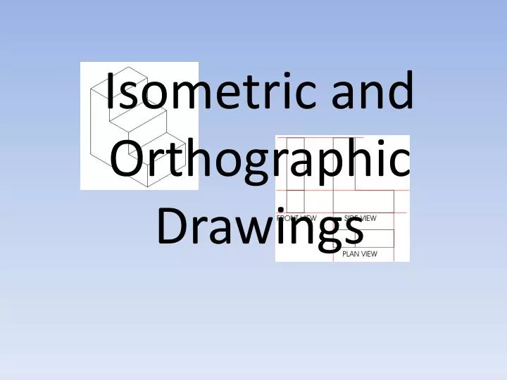
Isometric and Orthographic Drawings .

E N D
Isometric DrawingsUsing Isometric drawings is one of the simplest ways to give a 3-D representation while using only 2-D drawings. This has been the usual way of doing things before CAD allowed true 3-D work to be done. Many times an isometric drawing is used to compliment a 3 view orthographic drawing. See the sample below. You can see that it is a very simple drawing. This basic isometric drawing of the object gives a very good idea of what it looks like. If this is all that is needed then isometric works well. Unfortunately, as soon as you change anything, like the block's height, you'll need to redraw all four views.
Isometric Drawings • Everything humans make is designed. • However, not everything made is designed well. • You can probably tell when something is designed very well or very poorly. • As you develop your skills as a designer, you will be better prepared to identify good design. • Sketching is often done quickly, but neatly. • Practically everything designed starts with many sketches and then is drawn. • Drawings are made with special drawing instruments or a computer. • One of the most important skills a designer develops is the ability to sketch and draw. • Technical sketching is not art, it is primarily a method by which designs are developed. • It is also how designs are communicated with yourself and others.
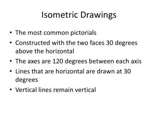
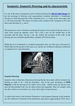
Purpose • How do reading the face of a clock and sketching isometric pictorials relate to each other? Picture a cube in your mind. All of the surfaces of the cube form right angles with their adjacent faces. If you were to draw an isometric pictorial of the cube, you would see that the edges point toward 2 and 8 o’clock, 4 and 10 o’clock, and 6 and 12 o’clock. This idea helps when sketching isometric pictorials on writing surfaces that do not have isometric grids. Isometrics are very common in Computer-Aided Design (CAD) programs and are only slightly more difficult to sketch than oblique pictorials. Procedure • In this activity, you will develop your isometric sketching skills by drawing views of objects that are already given in an isometric orientation. You will then apply your sketching skills throughout the remainder of the course. Before you begin, you must understand how an isometric view is called out. The image on the left represents a top, front, right side view isometric. The order is first face, second face, then third face. The same object is pictured again on the right, but shown in a top, left side, front view orientation.
Complete the isometric pictorial of the object pictured below. Use points and construction lines to layout the isometric sketches. DO NOT ERASE YOUR POINTS AND CONSTRUCTION LINES.
Make isometric sketches of the three objects pictured below. Sketch the objects in the same orientation that they are pictured in. Use points and construction lines to layout the isometric sketches.
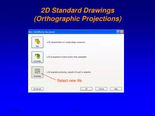
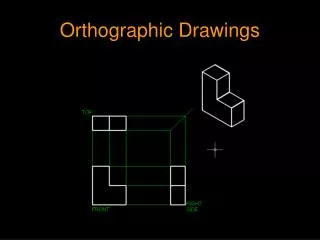
Orthographic Drawings • Orthographic Projection is a generally accepted convention for representing 3D objects using multiple 2D views of the front, top, bottom, back, and sides of the object. In practice, the minimal number of views possible is used to describe all the details of the object. Usually, the Front View, Top View, and a single Side View are sufficient and are oriented on the paper according to accepted convention.
This orthographic projection appears to have three separate drawings but they are the same L-shape. The first drawing is the front view (drawn looking straight at the front of the L-shape), the second is a drawing of the L-shape seen from the side and last of all a drawing from above known as a plan view. The red lines are faint guidelines and they are drawn to help keep each view in line, level and the same size.