Download
1 / 10
100 likes | 455 Vues
SCN plane. Transport plane. Management plane. Transport plane. IP Telephony plane. Transport Plane. IP Radio Access plane. IP Transport plane. TIPHON 17 Temporary Document 083 Sofia Antipolis, France . Definition of planes.

E N D
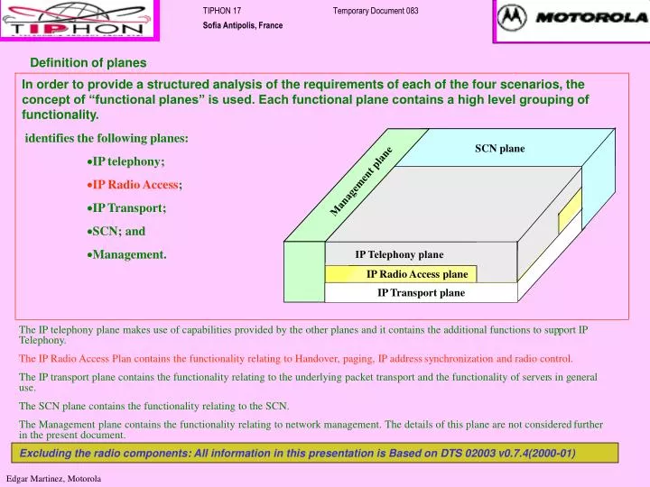
SCN plane Transport plane Management plane Transport plane IP Telephony plane Transport Plane IP Radio Access plane IP Transport plane TIPHON 17 Temporary Document 083 Sofia Antipolis, France Definition of planes • In order to provide a structured analysis of the requirements of each of the four scenarios, the concept of “functional planes” is used. Each functional plane contains a high level grouping of functionality. • identifies the following planes: • IP telephony; • IP Radio Access; • IP Transport; • SCN; and • Management. The IP telephony plane makes use of capabilities provided by the other planes and it contains the additional functions to support IP Telephony. The IP Radio Access Plan contains the functionality relating to Handover, paging, IP address synchronization and radio control. The IP transport plane contains the functionality relating to the underlying packet transport and the functionality of servers in general use. The SCN plane contains the functionality relating to the SCN. The Management plane contains the functionality relating to network management. The details of this plane are not considered further in the present document. Excluding the radio components: All information in this presentation is Based on DTS 02003 v0.7.4(2000-01) Edgar Martinez, Motorola
Mapping IP Telephony plane with Mobile/Wireless Aspects Mobile/Wireless Accepts Service Service Mobile Application Layer Service Control Call control Call control Access Interface Layer Bearer Wireless Interface Layer Media
TIPHON SCERRIOS The TIPHON Fixed/Wireless network architecture and the reference configurations that are necessary for: Scenario 1: the delivery of telephone calls which originate in an Internet Protocol (IP) network and are delivered to Switched Circuit Network (SCN); Scenario 2: the delivery of telephone calls which originate in SCN and are delivered in an IP network; Scenario 3: the delivery of telephone calls which originate in SCNs, routed through a IP network and finally delivered to an SCN; and Scenario 4 or 0: the delivery of telephone calls which originate and terminate in IP networks. such calls may be routed using an SCN. These four scenarios are part of TIPHON Phase 3 + Mobility. The TIPHON Fixed/Wireless architecture includes provision of information and facilities which are incidental to the delivery of telephone calls described above. The present IP network is applicable to equipment performing the roles of terminal, Gatekeeper/SIP Server, Radio Access node, Feature Servers and Gateways.
Radio Access Call direction Scenario1: PC or MT to Phone SCN VoIP Fixed/Wireless Network VoIP Network Interworking InterConnect Function InterConnect Function Function Scenario 1 enables calls from an IP terminal (called a “client”) through a Voice over IP (VoIP) network providing telephony services to a telephone connected to an SCN. shows this scenario in a schematic way. In the figure an InterWorking Function (IWF) is shown between the VoIP network function (i.e. the functionality of a VoIP domain) and the SCN function. An IP InterConnection Function (IPICF) is shown between two VoIP network functions. It is assumed that multiple administrative domains will exist within the IP network (and similar to SCN). Such domains will have their own policies on accounting, Quality of Service (QoS), etc. An IP interconnection function may be a null function if the two IP network functions belong to the same administrative domain.
Radio Access Call direction Scenario2: Phone to PC or MT SCN VoIP Fixed/Wireless Network VoIP Network Interworking InterConnect Function InterConnect Function Function This scenario enables a call from a telephone connected to the SCN to call a user connected to a VoIP network.
Radio Access Radio Access Scenario3: Phone or MS to Phone via IP InterConnect InterConnect VoIP Network Function Function SCN or Mobile Network SCN or Mobile Network Interworking Function Interworking Function Scenario 3 which enables the transport of calls that have originated in an SCN, are routed via a VoIP network, and terminate in (another) SCN. On a high-level this scenario can be considered as a concatenation of Scenario’s 1&2.
Radio Access Radio Access Scenario 4 and 0: Phone or MT to Phone via IP or ATM SCN Bridging SCN Bridging Function Function SCN InterConnect InterConnect VoIP Fixed/Wireless Network Function Function VoIP Fixed/Wireless Network VoIP Network InterConnect Function InterConnect Function Scenarios 4 & Scenario 0 enable calls originating on an IP terminal to terminate at an IP terminal. In Scenario 4 the SCN is used to transport the media and optionally the signaling of the call. In Scenario 0 the entire call is transported over IP networks. Because the IP clients have a richer interface than an traditional telephone, they must be able to negotiate other call parameters than a simple telephone call using a 64Kb codec. Hence this scenario is not a simple concatenation of Scenario’s 1&2. An SCN-IP Bridging function (SCNIPB) is employed, it may not interwork the media signaling but may (in some implementations) create a tunnel through the SCN domain(s) through which the native IP signaling may flow.
2. Locate 4. Locate domain for terminal for user B user B 5. Do you want a voice call from A? 8. Send media 9. Send media to to border border entity 4 entity 1 7. Setup QoS path 7. Setup QoS path between border between border entities 3 &4 entities 1 & 2 End to End Mobile Example SC SC 3. Set up a call between A & B 1. Setup CC CC voice& video call to B 6. Set up one audio and one video BC BC bearer between border entities 2&3 With QoS MC MC IP terminal A IP terminal B Wireless Access Border entity 4 Wireless Access Border entity 1 Border entity 3 Border entity 2
2. Locate 4. Locate domain for terminal for user B user B 5. Do you want a voice call from A? 8. Send media 9. Send media to to border border entity 4 entity 1 7. Setup QoS path 7. Setup QoS path between border between border entities 3 &4 entities 1 & 2 End to End Mobile to PC Example SC SC 3. Set up a call between A & B 1. Setup CC CC voice& video call to B 6. Set up one audio and one video BC BC bearer between border entities 2&3 With QoS MC MC IP terminal A IP terminal B Border entity 4 Wireless Access Border entity 1 Border entity 3 Border entity 2
Radio Access Radio Access LNP/DNS Service Network Dispatch Service WAP HLF Call direction Other Network Applications on IP e.g. E911, Toll services, LNP etc. LIDB 1-800 Equal Access IP Call Waiting Mobile Network IP Fixed/Wireless Network IP Network Services Node Interworking SCN or PSAP InterConnect Function InterConnect Function Function