Download
1 / 7
70 likes | 208 Vues
Drying System, IR and Temp Control. XL1500 Drying System. Components. The drying system system includes the following parts: IR lamps (400w) Fans 230v contactor Temperature controller Temperature sensor Thermo sensors. Process.

E N D
XL1500 Drying System Confidential
Components • The drying system system includes the following parts: • IR lamps (400w) • Fans • 230v contactor • Temperature controller • Temperature sensor • Thermo sensors Confidential
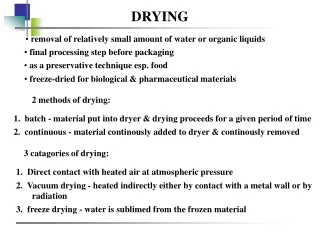
Process • The printed substrate moves under the drying system (IR). • When the printed substrate is exposed to the IR lamps, the drying process begins. • The fans work all the time (turned on/off by CB F8). The fans operate so that the warm air does not reach the print heads in order to avoid the heads from clogging. • The fans help to avoid damage to the substrateby cooling it down. • To provide the better drying, the exhaust pipes evacuate the warm air from the drying area (the exhaust system requirements are described in the XL1500 Site Preparation Guide). Confidential
System Requirements • The IR assy requires a 3-phase 230 VAC. • The IR is controlled by the temperature controller located in the PDU. • Fans are turned on/off via CB F8 located in the PDU. • The IR temperature controller receives 24 VDC from P5 in the PDU. • When the current temp. is higher then the temp. set point., 24 VDC is supplied to SSR 1,2,3 via fuse F16 that protects SSRs from overheating. • The signal to activate the IR comes via P4(short between pin 1 and 5). Confidential
System Requirements (Cont.) • IR lamps work only if : • Fans are working • 230 V hood contactor is activated. • All the thermo sensors are shorted and not indicating when the temperature exceeds 120°C. • 3 SSR’s (90A) are located inside the PDU and responsible for the IR’s working. Confidential
Examples Thermo sensor inside the IR assy 4 SSR’s inside the PDU Confidential