Download
1 / 22
220 likes | 373 Vues
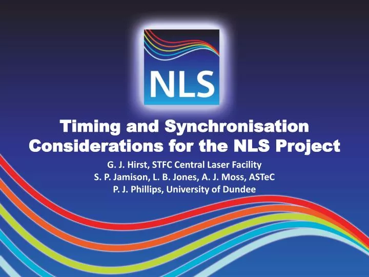
Timing and Synchronisation Considerations for the NLS Project. G. J. Hirst, STFC Central Laser Facility S. P. Jamison, L. B. Jones, A. J. Moss, ASTeC P. J. Phillips, University of Dundee. The NLS Project.

E N D
Timing and Synchronisation Considerations for the NLS Project G. J. Hirst, STFC Central Laser FacilityS. P. Jamison, L. B. Jones, A. J. Moss, ASTeCP. J. Phillips, University of Dundee
The NLS Project A science-driven proposal for an integrated suite of sourcesdelivering ~20fs FWHM pulses tuneable from THz to soft X-ray • Progress: • Launched April ’08 • Science case October ’08 • Developed science case July ’09and outline facility design • Conceptual design End of ’09 http://www.newlightsource.org/documents/NLS_Sci_Case.pdf
The NLS Project A science-driven proposal for an integrated suite of sourcesdelivering ~20fs FWHM pulses tuneable from THz to soft X-ray BMs and undulators (2.5-60meV)Conventional lasers + NLO (60meV-6eV), Laser HHG (6-50eV)Three seeded FELs (50-1000eV + harmonics) 200pC electron bunches from a photoinjector accelerated to2.25GeV in a cw SC 1.3GHz linac and compressed to ~200fs
Timing Output pulses will be equispaced with a nominal baselinepulse rate of 1kHz, rising to 10kHz, 100kHz and 1MHz • Factors affecting the exact rates will include: • Use of integer fractions of the master clock frequencywhich will be an integer fraction of the 1.3GHz RF • 1kHz-1MHz rates will be integer fractions of one another • Preference for the products of small primes (2n×3m)allowing simple subdivision and compatibility with awide range of resonant subsystems • Cooperation with international partners to allow thedevelopment of common commercial components
Clock Frequency and Bunch Rates Clocks based on fibre laser oscillators work best at ~200MHz 216.67MHz is a convenient (6th) subharmonic of 1.3GHz butinteger kilohertz rates are not subharmonics of this 216.67MHz ×3 ×26 ÷28 0.846MHz Phaseerror inputto PLLcontrol ÷23 105.8kHz 10MHz ÷(22×3) 8.816kHz ÷23 1.102kHz
Timing Summary • NLS time structures are science-driven Implementation details need careful thought but are not expected to present serious challenges
Gun laser PRIMARY: ~10 fs rms between FELs, lasers and THz/IR at the experiment Linac module Heater Bunch compressor Gun 3w cavity Collimator FEL THz/IR undulator NLS Synchronisation Requirements RF drive Endstation lasers HHG seed Laser-based diagnostics Heater Undulators User experiments Injector Linac Spreader
Linac module Heater Bunch compressor Gun 3w cavity Collimator FEL THz/IR undulator NLS Synchronisation Requirements RF drive Endstation lasers HHG seed Photoinjector Laser-based diagnostics Heater Undulators User experiments Injector Linac Spreader SECONDARY: Individual subsystem jitters low enough for stable source operation
Poweramp Pre-amp& gaincontrol Stretch& phasecontrol Broadbandosc Electronsync Compress Masterclock HHG seed laser Synchronisation of Lasers and FELs PLLcontrol Endstationlaser HHGchamber Phasesensor Electronbeam FEL undulators FEL beamline Clock distribution HHG seed laser locking Endstation laser locking Differential transport
FCS Implementation Principles • Sensors as close as possible to point-of-use • Actuators as close as possible to sources of noise • Sensing and control of the parameters of interest • Paths for fast, low-amplitude signals as short as possible • Burden on feedback control system minimised (e.g. passive stability maximised, deterministic variationsremoved into separate feed-forward systems)
Poweramp Pre-amp& gaincontrol Stretch& phasecontrol Broadbandosc Electronsync Compress Masterclock HHG seed laser Clock Distribution PLLcontrol Endstationlaser HHGchamber Phasesensor Electronbeam FEL undulators FEL beamline
At this stage it will suffice if at least one of these meets the NLS specification. Consider the pulsed laser scheme: Low noise clock, based on Er fibre laser locked to Rb/OCXO RF source below a few kHz Distribution fibre length stabilised by optical cross-correlation of retro-reflected signal Jitter may in fact beas low as 2fs per link Clock Distribution • Two femtosecond-jitter schemes have been demonstrated*, both distributing laser light (pulsed or cw) over optical fibres 3 fs overallfor 2 links * F Loehl et al, First prototype of an optical cross-correlation based fibre-link stabilization, DIPAC ’07 (2007) J W Staples et al, Demonstration of femtosecond-phase stabilization in 2km optical fiber, PAC ’07 (2007)
Poweramp Pre-amp& gaincontrol Stretch& phasecontrol Broadbandosc Electronsync Compress Masterclock Laser Locking HHG seed laser PLLcontrol Endstationlaser HHGchamber Phasesensor Electronbeam FEL undulators FEL beamline
Laser Locking • Ti:Sapphire laser oscillators have already been lockedboth to RF and to optical sources with ~1 fs jitter* • Complications in the NLS laser chains include: Wavelength tuning effects on the timing itself and on the sensor (should be deterministic) Noise from long paths,large pump lasers, cooling plant ... The Nyquist limit for noise sensing at low pulse rate Reconciling timing control with CEP stabilisation • Complications in the FEL amplification include: Bunch timing stability through the cascade chicane(s) SASE effects on the sensor (acceptable for true NLO ?) 5 fs target for endstation laser, 7 fs for HHG seed * R K Shelton et al, Subfemtosecond timing jitter between two independent, actively synchronized mode-locked lasers, Opt Letts 27 312 (2002), T R Schibli et al, Attosecond active synchronization of passively mode-locked lasers by balanced cross correlation, Opt Letts 28 947 (2003)
Poweramp Pre-amp& gaincontrol Stretch& phasecontrol Broadbandosc Electronsync Compress Masterclock HHG seed laser Differential Transport PLLcontrol Endstationlaser HHGchamber Phasesensor Electronbeam FEL undulators FEL beamline
Differential Transport • Direct feedback control is no longer possible, so stabilitymust be passive (or maintained by a proxy probe) • Beam path “ends” will vary from experiment to experiment, defined engineering standards off-line test facilities stability verification in advance • Stable few-metre interferometers are not uncommonand this is beyond the NLS stability requirement • But it is important to prevent final sensor “creep” back along the beam path
Poweramp Pre-amp& gaincontrol Stretch& phasecontrol Broadbandosc Electronsync Compress Masterclock HHG seed laser Synchronisation of Lasers and FELs PLLcontrol Endstationlaser HHGchamber Phasesensor Electronbeam FEL undulators FEL beamline INITIAL SETUP Proven technology, will be needed to establish seeded operation Removes the need for a new sensor, but results in a long unstabilised path
Differential Transport • Direct feedback control is no longer possible, so stabilitymust be passive (or maintained by a proxy probe) • Beam path “ends” will vary from experiment to experiment, defined engineering standards off-line test facilities stability verification in advance • Stable few-metre interferometers are not uncommonand this is beyond the NLS stability requirement • But it is important to prevent final sensor “creep” back along the beam path 3 fs on each path (~1 optical wave)4 fs for 2 links
Poweramp Pre-amp& gaincontrol Stretch& phasecontrol Broadbandosc Electronsync Compress Masterclock HHG seed laser Synchronisation of Lasers and FELs PLLcontrol Endstationlaser HHGchamber Phasesensor Electronbeam FEL undulators FEL beamline Clock distribution 3fs (demonstrated) HHG seed laser locking 7fs (target) Endstation laser locking 5fs (target) Differential transport4fs (target) QUADRATURE SUM~10fs BUT Needs high-resolution, single-shot soft X-ray phase sensor
Electron Beam Jitter Sources and Results • Reducing the two main contributors to the jitter by • independently powering the RF cavities in each cryomodule • reducing the power supply jitter in the bunch compressors to 10–5 Gun Jitter Parameters (rms) Solenoid Field 0.02e-3 T Gun Phase 0.1 degrees Gun Voltage 0.1% Charge 1% X Offset 0.025 mm Main linac cavities Phase (P) 0.01 degrees Bunch Comp. (B) 1e-5 fractional Voltage (V) 1-e4 fractional
Electron Beam Jitter Sources and Results • Reducing the two main contributors to the jitter by • independently powering the RF cavities in each cryomodule • reducing the power supply jitter in the bunch compressors to 10–5 Gun Jitter Parameters (rms) Solenoid Field 0.02e-3 T Gun Phase 0.1 degrees Gun Voltage 0.1% Charge 1% X Offset 0.025 mm Main linac cavities Phase (P) 0.01 degrees Bunch Comp. (B) 1e-5 fractional Voltage (V) 1-e4 fractional
Summary • NLS time structures are science-driven Implementation details need careful thought but are not expected to present serious challenges • Photon pulse synchronisation at the experiment will be keyto the success of NLS Many subsystems already meet specification, or are close Areas receiving attention include: Arrival time sensing for tuneable XUV pulses Laser pulse locking over extended paths with tuning Beam-based feedback for electron bunch arrival time Specifying and delivering stability at noise frequencies above the kilohertz Nyquist limit