Download
1 / 35
350 likes | 527 Vues
X-band accelerator Structure. LCPAC Feb. 20, 2004 T. Higo KEK. The most essential problem to be solved in accelerator structure. Stable operation at a high field is described in ICFA International Linear Collider Technical Review Committee Second Report 2003

E N D
X-band accelerator Structure LCPAC Feb. 20, 2004 T. Higo KEK LCPAC 2004 Structure (T. Higo)
The most essential problem to be solved in accelerator structure Stable operation at a high field is described in ICFA International Linear Collider Technical Review Committee Second Report 2003 Ranking 1 (R1) : R&D items needed for feasibility demonstration of the machine • For JLC-X/NLC, the validation of the presently achieved performance (gradient and trip rate) of low group velocity structures—but with an acceptable average iris radius, dipole detuning and manifolds for damping—constitutes the most critical Ranking 1 R&D issue. Tests of structures with these features are forseen in 2003. LCPAC 2004 Structure (T. Higo)
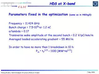
Practical R&D target • Gradient much more than 65MV/m was already obtained in a detuned structure but with very small a/l and without slots and manifolds. • Stable operation (namely 0.1BD / 60Hz X 1hr) at 65MV/m should be proved in a structure • with a/l as large as about 0.18 • with all slotted cells LCPAC 2004 Structure (T. Higo)
FY2003 Target items In collaboration with SLAC • Prove the high field performance to meet ITRC R1 requirement • Prove wake field control in 60cm high-power structures By KEK • Invoke high field test of structure at KEK • Fabricate actual-size structure in Japan LCPAC 2004 Structure (T. Higo)
Evolution from RDDS1 to H60VG4S17 In 2003 0.9m 0.6m a/l 0.18 0.17 Until 2003 1.8m 0.9m 2p/3 5p/6 LCPAC 2004 Structure (T. Higo)
Structure parameter evolution in 2003 Ls a/l vg/c Pin Enl Structure m % MW MV/m Reduce structure length(1.8 0.9) for low vg (12% 5~3%) 2003 Feb. 3 0.9 0.18 5-3 75 65(H90VG5N etc.) Reduce structure length, reduce power & pulse heating 2003 ~Spring: 4 0.6 0.18 3-1 69 65 H60VG3S18 Reduce a/l for Rsh up to reduce power & reduce upstream field 2003 ~Fall:50.6 0.17 4-1 59 65 H60VG4S17 LCPAC 2004 Structure (T. Higo)
Parameter evolution in 60cm structures for further improving high-field performance Naming for example on H60VG4S17 H High phase advance structure (150deg/cell) 60 60cm long VG Group velocity at upstream side 4 Percent of light speed S With slots and manifolds 17 a/l=0.17 4 5 VG3A18 ILT Round iris VG3S18Elliptical iris VG3S17 Elliptical iris VG4S17 Elliptical iris • H60VG3S18 • Iris roundelliptical • a/l 0.180.17 • Vg/c 3%start at 4% LCPAC 2004 Structure (T. Higo)
FY2003 Actual activities • Refinement and production of HDDS cells for structures tested at NLCTA • H60VG3S18 and H75VG4S18 • H60VG4S17-I, II and H60VG4S17-III • Prepare for H60VG4SL17-A,B • Fabrication of 60cm structure in Japan • Setup of GLCTA high power test area by ATF • Establishment of calculation of cell frequencies • Initialization of HDDS cell production studies by parties other than KEK LCPAC 2004 Structure (T. Higo)
High field test of 60cm structures High power test all at NLCTA Structures are SLAC/KEK SLAC made FNAL made For HDDS evaluation 4 -- H60VG3N-6C 4 -- H60VG3S18 5 -- H60VG4S17-I 5 -- H60VG4S17-III • For early tasting of a/l=0.17 • H60VG3R17 • H60VG4R17 • For fabrication by FNAL • -- H60VG3R18(FXB) • -- H60VG3S17(FXC) Keep close collaboration with FNAL structure group in addition to SLAC LCPAC 2004 Structure (T. Higo)
High field studies of 60cm 5p/6-mode structuresin which KEK cells are/were used Structure code In Coupler Results or status 4 H60VG3N-6C ILT High power test finished 4 H60VG3S18 MC High power test finished • H75VG4S18 MC Completed 5 H60VG4S17-I MC High power test finished 5 H60VG4S17-II WG Cells were produced 5 H60VG4S17-III(1) WG Under assembly 5 H60VG4S17-III(2) WG Cell under production • H60VG4SL17 A,B WG For wake field control suspended Input coupler type: ILT=in line taper, MC=mode converter, WG=waveguide LCPAC 2004 Structure (T. Higo)
HDDS cell production LCPAC 2004 Structure (T. Higo)
Basic specification for HDDS cell • We design the fabrication based on precision milling + diamond turning. • Turning precision is specified as 2 microns in diameter. Dimensions among milled 3D geometries are within 10 microns. Frequencies can be controlled within a few MHz, meeting dipole frequency tolerance of s~5MHz • Concentricity better than 5 microns Alignment tolerance of several microns becomes feasible. LCPAC 2004 Structure (T. Higo)
Electric field / Magnetic field 4 2 3 1 Esurface HsurfaceDTpulse We need to avoid additional local field enhancement due to non-smoothness especially at red areas. Special care is taken at points (2,3,4) where smooth junction is difficult due to the junction between milling and turning LCPAC 2004 Structure (T. Higo)
Ensuring junction between milling and turning connecting at a small angle • Use of tapered milling tool • Precise vertical positioning • Checking profile by stylus Established cell fabrication technique based on precision milling + diamond turning Junction Profile measurement LCPAC 2004 Structure (T. Higo)
Burrs are safely removed Not easy for the machining to be completely free from burrs but they are in low field area so that they can be hand deburred. SEM from C. Pearson (SLAC) LCPAC 2004 Structure (T. Higo)
Scratches are smoothed by chemical etching process Present quality on surface scratches: Scratches are smoothed by etching process as shown left. This example is much larger than our acceptance level inspected with a low magnification optical microscope. As of machined After chemical etching LCPAC 2004 Structure (T. Higo) SEM from C. Pearson (SLAC)
Summary of breakdown rate of recent structures • Following page shows plots of the breakdown rates of structures tested in 2003 as function of accelerator field. • The performance near the nominal field of 65MV/m without beam loading was studied. • The pulse length is 400ns flat pulse, except for the point indicated as “design pulse shape” where the ramping pulse shape needed for the beam loading compensation. • Requirement of 0.1 breakdown per hour is equivalent to 1 breakdown in 2 million pulses at the present repetition rate of 60Hz. LCPAC 2004 Structure (T. Higo)
Structure High Gradient Performance Summary (Breakdown Rate -vs- Unloaded Gradient with 400 ns Square Pulses) LCPAC 2004 Structure (T. Higo) C. Adolphsen (SLAC) Jan. 2004
H60VG3S18 Processing history First full-HDDS cell structure LCPAC 2004 Structure (T. Higo)
H60VG3S18 BD position 65MV/m 70MV/m Breakdowns located mainly at upstream cells LCPAC 2004 Structure (T. Higo) Data from C. Adolphsen SLAC
a/l 0.18 0.17 and vg/c 3% 4% H60VG3S18 H60VG4S17 Reduce surface field at upstream end • Increase Rs 59 61MW/m • Reduce power 69 59MW • Reduce magnetic field • Reduce pulse temperature rise LCPAC 2004 Structure (T. Higo)
H60VG4S17 Process history C. Adolphsen SLAC 040126 Eacc [MV/m] LCPAC 2004 Structure (T. Higo) Data from C. Adolphsen SLAC
Pulse shapes for high power test at NLCTA Input power with flat pulse Input power with ramp for Beam loading compensation Time (ns) from C. Adolphsen SLAC Time (ns) LCPAC 2004 Structure (T. Higo) Data from C. Adolphsen SLAC
Dependence on input pulse shape Various pulse shape Ramped pulse shape Back to flat 400ns • BD rate significantly decreased with ramped pulse shape • BD localized, BD position switched to another cell • Many soft events, later than 100ns – similar to those due to pulse heating • Need to study with a normal structure LCPAC 2004 Structure (T. Higo) Data from C. Adolphsen SLAC
Structure High Gradient Performance Summary (Breakdown Rate -vs- Unloaded Gradient with 400 ns Square Pulses) LCPAC 2004 Structure (T. Higo) C. Adolphsen (SLAC) Jan. 2004
High field test result summary • Structure with present HDDS cells show similar performance to those of non-slotted structures. • Low surface electric field at upstream cells seems effective to reduce BD rate. • BD rate scales exponentially as accelerator field, roughly 5MV/m per decade. • Pulse shaping for beam loading compensation is effective to reduce BD rate. • Rates scatteres from structure-to-structure probably related to fabrication/installation processes. Ii is important to reproduce good ones by improving practical processes with more structures under the present structure design. LCPAC 2004 Structure (T. Higo)
Proof of wake field suppression Need to prove • Wake field suppression by damped-detuned scheme Frequency control • Structure alignment based on HOM monitoring Structure straightness and 3D geometry concentricity w.r.t. beam hole etc. • The feasibility of wake field control was already proved in 1.8m structure. • This was not in the high priority now and we suspended the wake-field program in 2003. • After establishing high field performance, we should come back to this issue and actually prove in our latest structure design. • But there are some related experiences acquired in HDDS cell production as shown in the following two pages. LCPAC 2004 Structure (T. Higo)
Frequency smoothness in H60VG4S17 production and feasibility to control F1 Std dev = ~0.5MHz Std dev = ~1MHz It seems that we have a feasibility to control within 1MHz sigma. To be confirmed in wake-field test structure. LCPAC 2004 Structure (T. Higo)
Fabrication of 60cm structure KX01 (H60VG3N) • Diamond turning by an industry • Chemical etching at KEK • Diffusion bonding and brazing in hydrogen furnace at a company • Vacuum baking in a klystron factory • Now tuning and high-power test at KEK LCPAC 2004 Structure (T. Higo)
Actual-size structure fabrication • Gain experience of fabrication of actual-size structure • Study high-field performance at GLCTA • Try to find a way to improve high-field performance through fabrication technology • Made first 60cm HDS structure (KX01) with parameters H60VG3N and now under tuning LCPAC 2004 Structure (T. Higo)
GLCTA structure point of view • Activities of 2003 • Moved high-field setup from AR-south to ATF area • Refurbished the system in control and data taking • Restarted high power study • Goal of 2004 • Actually process structures to high field during long-term (>>100hours) • Breakdown related data are recorded and analyzed through operation • Various components will be developed and used, such as waveguide flanges, low-loss waveguides, RF load, etc. LCPAC 2004 Structure (T. Higo)
GLCTA at present • Two klystrons are • delivering ~60MW, • 400ns to structure • T53VG3F is sitting now • Preparing control and • measurement system • Install KX01 soon • SLAC helps such as • acoustic meas.(now) • low loss waveguides • (in future) • etc. LCPAC 2004 Structure (T. Higo)
Conclusion of 2003 structure development • Established HDDS cell fabrication technique. • Typically 60cm structures show BD rate at nominal field of 65MV/m within a factor of 5or so w.r.t. the requirement. • On the other hand, almost all structures met BD rate requirement at 60MV/m. We understand it is worthwhile to study the feasibility to start with a moderately low field operation. • BD rate nearly met the requirement when operated with a pulse shape for beam-loading compensation. • Prepared a high power test facility GLCTA. LCPAC 2004 Structure (T. Higo)
Developments in early 2004 • Acquire more statistics with the present design (H60VG4S17) structures with SLAC to have a clear view of the present design. • This process is pursued by applying any improvement offabrication, installation and processing procedures. • Develop and really make GLCTA serve as high field study facility. LCPAC 2004 Structure (T. Higo)
Developments in second half of 2004 • Once foresee the establishment of high field performance, we discuss the next study items such as • Proving the wake field performance with SLAC in the present design structure. • Or going into studies on mass production of cells and structures. • Otherwise, we focus on establishing good high field performance. LCPAC 2004 Structure (T. Higo)