Download
1 / 14
140 likes | 674 Vues
NexGen Burnthrough Test Apparatus. Laboratory Setup Guidelines. System Schematic. Pressure Regulator (supplied) has 1” NPT Female connection for compressed air line (1”). Base – Not Supplied. Connect fuel line here (1/4” pipe or flexible tubing with ¼” swagelok connection)

E N D
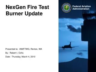
NexGen Burnthrough Test Apparatus Laboratory Setup Guidelines
System Schematic Pressure Regulator (supplied) has 1” NPT Female connection for compressed air line (1”) Base – Not Supplied Connect fuel line here (1/4” pipe or flexible tubing with ¼” swagelok connection) Supplied with ¼” swagelok male connection Not Pictured: two electrical leads (supplied) to igniters – connect to transformer box (not supplied) Connect air line here
Compressed Air Supply • Compressor minimum requirements: • Constant line pressure of at least 57-60 psig • Mass flow rate of 63 SCFM (standard cubic feet per minute) • Burner comes supplied with a pressure regulator upstream of the sonic orifice. To connect the burner to your compressed air supply, a 1” air line will be required • Regulator has 1” NPT female connection. A flexible air line will make connections easier, we use a steel braided 1” flex-line. • Before receiving the burner, it may be wise to measure the temperature of your airflow as a function of time while your compressor is running, for a time duration about equal to that of a burnthrough test. This will tell you if you will have fluctuations in air temperature during a test. The temperature should be approx 50-60 deg. F. It is recommended to install an in-line water cooled heat exchanger to dampen out temperature fluctuations. We use McMaster Carr p/n 43865K78 (www.mcmaster.com) with a condensate separator, McMaster Carr p/n 43775K55
Pressurized Fuel System Pressure Regulator (in the range of 0-150 psig) e.g., Bellofram Type 70 Pressure Regulator, 2-150 psig, max 250 psig inlet, approx $79 Solenoid or manual ball valve Solenoid or manual ball valve Needle valve to control venting Pressurized Air Inlet Fuel Fill Vent to lab or outdoors Compressed gas (from bottled Nitrogen or Air, or air compressor, if it is capable Vent Pressure Vessel (for example, McMaster-Carr p/n 1584K7, ASME-Code Vertical Pressure Tank W/O Top Plate, 15 Gallon Capacity, 12" Dia X 33" L, $278.69) or any suitable pressure vessel that can withstand pressures of around 150 psig. High pressure liquid level sight gauge (We use McMaster Carr p/n: 3706K23) Air/N2 @ ~120 psig Fuel This schematic is pretty basic. You can supplement this design with whatever instrumentation you would like to obtain the required data or to make for easier operation. Some examples would be a pressure transducer, remotely operated solenoid valves, fuel flow meter, etc. Fuel Outlet Nozzle 5.5 GPH 80 deg-PL Solenoid or manual ball valve Ice Bath H2O
Controls + 28 VDC S1 S2 S3 S4 S5 28 VDC Switches (S1-S5) Air On Ignition On Fuel On Tank Fill Tank Vent - + 120 VAC R1 R2 R3 R4 R5 Solid state relays (R1-R5) - 1” Normally closed solenoid valve ¼” normally closed, fuel rated solenoid valve ¼” normally closed solenoid valve for tank pressurization ¼” normally closed solenoid valve for tank de-pressurization Transformer for igniters Control Box
Burner Setup Checklist • Fuel Temperature • Fuel temperature must be measured at the back of the burner, as indicated on slide 3 • A 1/8” sheathed type-K thermocouple inserted into a ¼” Swagelok t-connection should be inserted into the fuel line as indicated on slide 3 • The liquid fuel should be cooled in an ice bath, as shown on slide 4. This can be achieved by using a tub or bucket filled with an ice-water mixture. Fuel run through copper tubing coils will cool to approximately 32-40°F by the time it reaches the fuel thermocouple. The length of the coils in the bath at the tech center is approximately 37 feet (the length of the coils will vary depending on where the ice bath is located) • The initial temperature of the fuel should be around 32-40°F. During the length of a test, the fuel temperature increase should not be greater than 10°F (the maximum increase seen at the tech center was around 5°F). • Insulation should be used to cover the ice bath, fuel, and air lines to prevent heating of the fuel or air by flame radiation. See slide 5. • Fuel Pressure • Fuel pressure is to be measured in the same manner as temperature, as indicated on slide 3. • Air Temperature • To regulate the air temperature, an in-line water cooled heat exchanger can be used to dampen out fluctuations in air temperature. McMaster-Carr p/n 43865K78 and 43775K55 is used at the tech center. This device keeps the change in air temperature down to approximately 5°F, with an initial temperature of approximately 50-60°F (depending on the water temperature). • An ice bath can be used to chill the water used as the heat exchange medium for the heat exchanger. This will expedite the cooling process, and will also help to maintain a very steady air temperature. • Cone • The top side of the cone is marked with three hash marks to align the cone with the draft tube (slide 7). Use these marks as a guide, but not to replace proper measurement and orientation.
Fuel solenoid valve Fuel pressure gauge Fuel thermocouple (1/8” dia. K-type)
¼” copper tubing coils (we use 2 coils for fuel cooling, 2 coils to cool the water for the air heat exchanger) Fuel in / out Water in / out
Ice Bath Insulation Blankets
Ice Bath Fuel Lines Air Line Fuel pressure gauge and T/C
Contact Info Robert I. Ochs DOT/FAA Technical Center BLDG 287 Atlantic City Int’l Airport, NJ 08405 robert.ochs@faa.gov 609-485-4651