Download
1 / 21
210 likes | 386 Vues
PantherBot Tool Changer. Project Review Presentation. Mechanical Engineering Design 2 – MAE 4194 28 January 2009 Jameson L. Tai William Rae Justin Nunn In Partnership with: .

E N D
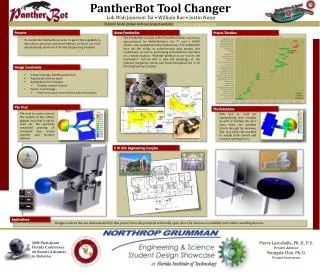
PantherBot Tool Changer Project Review Presentation Mechanical Engineering Design 2 – MAE 4194 28 January 2009 Jameson L. Tai William Rae Justin Nunn In Partnership with: All logos in this presentation are courtesy of the Florida Institute of Technology Robotics and Spatial Systems Laboratory and the Florida Tech Office of Creative Services.
Project Objectives Overview (Image Source: Robotics and Spatial Systems Laboratory (RASSL))
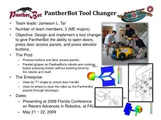
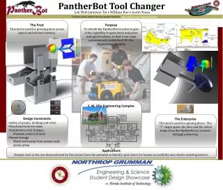
Project Purpose • The purpose of our project is to retrofit the PantherBot in order to give it the capability to open doors and press wall panel buttons, so that it can roam autonomously inside the F. W. Olin Engineering Complex.
Project Overview • Design tools that allow PantherBot autonomous access around Olin Engineering Complex • Safe for people and robot • Doesn’t damage school facilities (Image Source: Robotics and Spatial Systems Laboratory (RASSL))
Work to Date (Image Source: File Photo; Taken by Jameson L. Tai)
Work to Date • Finalized design, completed drawing package and received approval for fabrication of button pushing tool • Found materials left from other projects and ordered needed parts for button pushing tool • Left over materials have allowed us to cut costs by close to 50% for this tool
Work to Date • Identified flaw with original door tools • Redesigned tool to correct problem • Prototyped new door opening tool to prove concept and determine best wheel size and configuration
Work to Date • Performed analysis on redesigned tool • Completed drawing package for door opening tool • Identified materials already on hand for production
Current Progress (Image Source: RASSL)
Current Progress • Tool 1 • Final drawing package approved, and ready for fabrication • Research on foam tips for button pushing • Tool 2 • Prototyping new design • Finalizing design
Current Progress • Part Order forms • Materials for Tool 1 finalized and submitted • Materials for Tool 2 for parts not already on-hand • Beginning fabrication • Tool 1 ready for fabrication as materials arrive
Fabrication and Testing Planning and Execution (Image Source: http://www.sharpmachinetools.com/millingmachines/1054%20mill%20w%20dro.jpg)
Fabrication Plans • Timeline shift • Fabrication and Testing deadlines moved • Button Pushing Tool • Drawing package approved • Requisition form for parts submitted • Door Opening Tool • Drawing packing completed, awaiting approval • Analysis in-progress • Parts list ready to submit requisition form pending approval
Fabrication Plans • Revised timeline to reflect new design • Merging original Tool 2 and Tool 3 • Reduced parts list • Lower cost to fabricate • Requires less time to fabricate • Moving on with fabrication of Tool 1 as planned • Revised door opening tool construction to begin in two weeks
Tool 1 Fabrication Plan Most machining done in Building 538 Complex geometries for parallel gripper replaced by premade U-Channels Minor welding will be done, welding marked on drawing package Design approved for fabrication by Dr. Larochelle
Tool 2 Fabrication Plan Most machining done in Building 538 Complex geometries for parallel gripper replaced by premade U-Channels and skate wheel Will share materials used by Tool 1 to minimize parts cost Minor welding will be done, welding marked on drawing package
Holder 1 Fabrication Plan Single sheet of sheet metal bent four times to acquire a C-shape enclosure for Tool 1 Mounted to the front side of the PantherBot, away from sonar and laser range finders
Holder 2 Fabrication Plan Single piece of sheet metal with metal hooks which will secure Tool 2 from movement during transport Allow easy access for the robotic arm Mounted to the front side of the PantherBot, on the opposite end from Holder 1.
Coding/Testing • Coding and testing will occur together • Coding practices and tests tools and holders made • attack angles on optimizing the door-opening angles • proper distance the Schunk robotic arm should be away from the button/access panel