Download
1 / 77
960 likes | 1.68k Vues
Introduction to Analog And Digital Communications. Second Edition Simon Haykin, Michael Moher. Chapter 10 Noise in Digital Communications. 10.1 Bit Error Rate 10.2 Detection of a Single Pulse in Noise 10.3 Optimum Detection of Binary PAM in Noise 10.4 Optimum Detection of BPSK

E N D
Introduction to Analog And Digital Communications Second Edition Simon Haykin, Michael Moher
Chapter 10 Noise in Digital Communications 10.1 Bit Error Rate 10.2 Detection of a Single Pulse in Noise 10.3 Optimum Detection of Binary PAM in Noise 10.4 Optimum Detection of BPSK 10.5 detection of QPSK and QAM in Noise 10.6 Optimum Detection of Binary FSK 10.7 Differential Detection in Noise 10.8 Summary of Digital Performance 10.9 Error Detection and Correction 10.10 Summary and Discussion
Two strong external reasons for the increased dominance of digital communication • The rapid growth of machine-to-machine communications. • Digital communications gave a greater noise tolerance than analog • Broadly speaking, the purpose of detection is to establish the presence of an information-bearing signal in noise.
Lesson 1: the bit error rate is the primary measure of performance quality of digital communication systems, and it is typically a nonlinear function of the signal-to-noise ratio. • Lesson 2: Analysis of single-pulse detection permits a simple derivation of the principle of matched filtering. Matched filtering may be applied to the optimum detection of many linear digital modulation schemes. • Lesson 3: The bit error rate performance of binary pulse-amplitude modulation (PAM) improves exponentially with the signal-to-noise ratio in additive white Gaussian noise. • Lesson 4: Receivers for binary and quaternary band-pass linear modulation schemes are straightforward to develop from matched-filter principles and their performance is similar to binary PAM. • Lesson 5: Non-coherent detection of digital signals results in a simpler receiver structure but at the expense of a degradation in bit error rate performance. • Lesson 6: The provision of redundancy in the transmitted signal through the addition of parity-check bits may be used for forward-error correction. Forward-error correction provides a powerful method to improve the performance of digital modulation schemes.
10.1 Bit Error Rate • Average bit error rate (BER) • Let n denote the number of bit errors observed in a sequence of bits of length N; then the relative frequency definition of BER is • Packet error rate (PER) • For vocoded speech, a BER of to is often considered sufficient. • For data transmission over wireless channels, a bit error rate of to is often the objective. • For video transmission, a BER of to is often the objective, depending upon the quality desired and the encoding method. • For financial data, a BER of or better is often the requirement.
SNR • The ratio of the modulated energy per information bit to the one-sided noise spectral density; namely, • The analog definition was a ratio of powers. The digital definition is a ratio of energies, since the units of noise spectral density are watts/Hz, which is equivalent to energy. Consequently, the digital definition is dimensionless, as is the analog definition. • The definition uses the one-sided noise spectral density; that is, it assumes all of the noise occurs on positive frequencies. This assumption is simply a matter of convenience. • The reference SNR is independent of transmission rate. Since it is a ratio of energies, it has essentially been normalized by the bit rate.
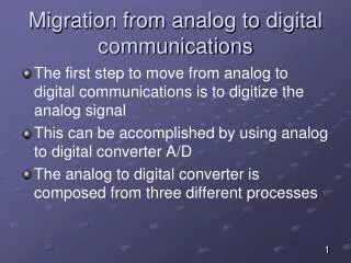
10.2 Detection of a Single Pulse in Noise • The received signal consists solely of white Gaussian noise • The received signal consists of plus a signal of known form. • For the single-pulse transmission scheme • The received signal : • The first integral on the right-hand side of Eq. (10.5) is the signal term, which will be zero if the pulse is absent, and the second integral is the noise term which is always there. Fig. 10.1
Back Next Fig. 10.1
The noise sample at the output of the linear receiver has • A mean of zero. • A variance of • A Gaussian distribution, since a filtered a Gussian process is also Gaussian (see Section 8.9). • The signal component of Eq.(10.5) • Schwarz inequality for integrals is
With defined by Eq.(10.1), the signal component of this correlation is maximized at This emphasizes the importance of synchronization when performing optimum detection.
10.3 Optimum Detection of Binary PAM in Noise • Consider binary PAM transmission with on-off signaling • The output of the matched filter receiver at the end of the kth symbol interval is • Since the matched filter wherever it is nonzero, we have Fig. 10.2
Back Next Fig. 10.2
BER performance • Consider the probability of making an error with this decision rule based on conditional probabilities. If a 1 is transmitted, the probability of an error is Fig. 10.3
Back Next Fig. 10.3
Type II error. • An error can also occur if a 0 is transmitted and a 1 is detected • The probability regions associated with Type I and Type II errors are illustrated in Fig. 10.5. The combined probability of error is given by Bayes’ rule (see Section 8.1) Fig. 10.4
Back Next Fig. 10.4
A priori probability • The average probability of error is given • Average probability of error Fig. 10.5
Back Next Fig. 10.5
Our next step is to express this probability of bit error in terms of the digital reference model. • To express the variance in terms of the noise spectral density, we have, from Eq.(10.9), that • To express the signal amplitude A in terms of the energy per bit , we assume that 0 and 1 are equally likely to be transmitted. Then the average energy per bit at the receiver input is
Nonrectangular pulse shapes • The received signal • P(t) is a normalized root-raised cosine pulse shape
Applying the matched filter for the kth symbol of to Eq.(10.31), we get • Under these conditions, and the BER performance es the same as with rectangular pulse shaping Fig. 10.6
Back Next Fig. 10.6
10.4 Optimum Detection of BPSK • One of the simplest forms of digital band-pass connunications is binary phase-shift keying. With BPSK, the transmitted signal is Fig. 10.7
Back Next Fig. 10.7
Detection of BPSK in noise • The signal plus band-pass noise at the input to the coherent BPSK detector • The output of the product modulator • The matched filter
The output of the integrate-and-dump detector in this • The noise term in Eq.(10.40) is given by
In digital communications, the objective is to recover the information, 0s and1s, as possible. Unlike analog communications, there is no requirement that the transmitted waveform should be recovered be recovered with minimum distortion. • Performance analysis • If we assume a 1 was transmitted and then the probability of error is • The bit error rate
The analysis of BPSK can be extended to nonrectangular pulse shaping in a manner similar to what occurred at baseband. For nonrectangular pulse shaping, we represent the transmitted signal as
10.5 detection of QPSK and QAM in Noise • Detection of QPSK in niose • That QPSK–modulated signal
Using in-phase and quadrature representation for the band-pass noise, we find that the QPSK input to the coherent detector of Fig.10.8 is described by • The intermediate output of the upper branch of Fig.10.8 is • The output of the lower branch of the quadrature detector is Fig. 10.8
Back Next Fig. 10.8
For the in-phase component, then the mean output is • The first bit of the dibit is a 1 then • The probability of error on the in-phase branch of the QPSK signal is
The average energy by bit may be determined from • The bit error rate with after matched filtering is given by
In terms of energy per bit, the QPSK performance is exactly the same as BPSK • Double-sideband and single-sideband transmission, we found that we could obtain the same quality of performance but with half of the transmission bandwidth. With QPSK modulation, we use the same transmission bandwidth as BPSK but transmit twice as many bits with the same reliability. • Offset-QPSK or OQPSK is a variant of QPSK modulation • The OQPSK and QPSK, the bit error rate performance of both schemes is identical if the transmission path does not distort the single. • One advantage of OQPSK is its reduced phase variations and potentially less distortion if the transmission path includes nonlinear components such as an amplifier operating near or at saturation. Under such nonlinear conditions, OQPSK may perform better than QPSK.
Detection of QAM in noise • The baseband modulated signal be represented by Fig. 10.9 Fig. 10.10
Back Next Fig. 10.9
Back Next Fig. 10.10
There are two important differences that should be noted : • Equation (10.57) represents a symbol error rate. • With binary transmission with levels of +A and –A, the average transmitted power is • The probability of symbol error in terms of the digital reference SBR is • We may use independent PAM schemes on the in-phase and quadrature components. That is to say, one PAM signal modulates the in-phase carrier and the second PAM signal modulates the quadrature carrier • Due to the orthogonality of the in-phase and quadrature components, the error rate is the same on both; and the same as the baseband PAM system. Fig. 10.11
Back Next Fig. 10.11
10.6 Optimum Detection of Binary FSK • The transmitted signal for is • The two matched filters are • The corresponding waveforms are orthogonal Fig. 10.12
Back Next Fig. 10.12
Let the received signal be • Then the output of the matched filter corresponding to a 0 is • The noise component at the output of the matched filter for a 0 is
The output of the filter matched to a 1 is • The noise component of Eq.(10.65) • By analogy with bipolar PAM in Section 10.3, the probability of error for binary FSK is
The BER in terms of the digital reference model is • In general, we see that antipodal signaling provides a dB advantage over orthogonal signaling in bit error rate performance.
10.7 Differential Detection in Noise • band-pass signal at the output of this filter • The output of the delay-and-multiply circuit is Fig. 10.13 Fig. 10.14
Back Next Fig. 10.13
Back Next Fig. 10.14
Since in a DPSK receiver decisions are made on the basis of the signal received in two successive bit intervals, there is a tendency for bit errors to occur in pairs.