Download
1 / 11
120 likes | 264 Vues
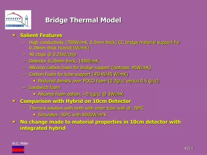
Bridge Thermal Model. Salient Features High conductivity (700W/mK, 0.5mm thick) CC bridge material support for 0.28mm thick hybrid(1W/mK) 40 chips @ 0.25W/chip Detector 0.28mm thick, 148W/mK Allcomp carbon foam for bridge support (isotropic 45W/mK)

E N D
Bridge Thermal Model • Salient Features • High conductivity (700W/mK, 0.5mm thick) CC bridge material support for 0.28mm thick hybrid(1W/mK) • 40 chips @ 0.25W/chip • Detector 0.28mm thick, 148W/mK • Allcomp carbon foam for bridge support (isotropic 45W/mK) • Carbon Foam for tube support (45/45/45 W/mK) • Reduced density over POCO foam (0.2g/cc versus 0.5 g/cc) • Sandwich foam • Allcomp foam option, ~0.1g/cc @ 3W/mK • Comparison with Hybrid on 10cm Detector • Thermal solution with both with inner tube wall at -28ºC • Simulates -30ºC with 8000W/m2K • No change made to material properties in 10cm detector with integrated hybrid VG 1
10cm Detector-No Bridge Old model parameters VG 2
10cm Detector-No Bridge • Material Properties • See previous slide (#2) • 40 chips per detector, 80 total • 0.25W/chip Q (Si)=0W • Tube inner surface -28ºC, no convection coefficient • Interest in ΔT from chip and detector surface to tube surface • Peak chip temperature • Middle hybrid region: -20.5ºC • Peak Detector • Middle hybrid region: -21.5ºC • ΔT in region of max gradient: 6.5ºC VG 3
10 CM Wide Stave-No Bridge • Solution • Replaced honeycomb core with Allcomp carbon foam (<0.2g/cm3: 45W/mK) • Also, replaced POCO foam tube support with same foam • Peak Chip Temp: -22.7ºC • Peak Detector: -24ºC • ΔT (referenced to tube wall) • 4ºC VG 4
10 CM Wide Stave-No Bridge • Solution: Simulate “outer” long strip detector • One upper and power hybrid for 10cm detector • 20 chips @ 0.25W/chip • Coolant tube inner surface: -28ºC • Materials, see slide (#2) • Detector • Peak temp beneath hybrid: -24.8ºC • ΔT in region of max gradient: 3.2ºC • Chip Peak Temp: -24.1ºC VG 5
Thermal Bridge Model (1/2 of 10cm) 1mm air gap for bridge Wire bonds, simulated as thin solid, reduced K to 97W/mK 10cm Al Cooling tube 0.21mm ID Chips 0.38mm thick (148W/mK) Separation between facings 4.95mm Foam bridge support VG 6
Bridge Thermal Model Enclosed bridge model in an air box. Air participates only through pure conduction. Air fills all cavities not occupied by a solid Air box VG 7
Model Parameters Cable and adjacent adhesive layers modeled as single layer 0.227mm and K=0.31W/mK VG 8
Solution with -30ºC Tube 8000 W/m2K 0.5W/chip Q (Si)=0 Slight asymmetry caused by variance in interior coolant wall temperature Chip peak=-16.5ºC Detector max=-21.4ºC VG 9
Solution with -30ºC Tube 8000 W/m2K 0.25W/chip Q (Si)=0 Slight asymmetry caused by variance in interior coolant wall temperature Chip peak=-23.3ºC Detector max=-25.8ºC VG 10
Solution with -30ºC Tube 8000 W/m2K 0.25W/chip Q (Si)=0 Sandwich foam core 3W/mK, density ~0.06 g/cm3 Bridge foam and tube foam 45W/mk, density ~0.2 g/cm3 (no POCO foam) Peak chip=-21.8ºC Peak detector temp -24.2ºC Wire bonds 97W/mK VG 11