Download
1 / 41
410 likes | 533 Vues
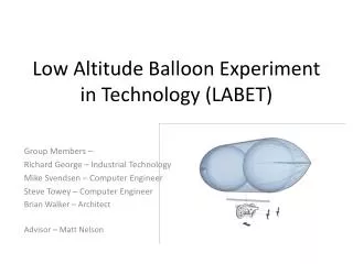
Low Altitude Balloon Experiments in Technology (LABET) Version IV. EcpE 492: Dec09-14 Engr 467: LABETIV_SP09 Henri Bai Steve Beckert Ian Moodie Mike Rau Matthew Nelson, Advisor John Basart, Advisor December 9, 2009. Problem Statement.

E N D
Low Altitude Balloon Experiments in Technology (LABET)Version IV EcpE 492: Dec09-14 Engr 467: LABETIV_SP09 Henri Bai Steve Beckert Ian Moodie Mike Rau Matthew Nelson, Advisor John Basart, Advisor December 9, 2009
Problem Statement As real-world engineering becomes more complex and requires the skills of many disciplines, it is difficult to accurately simulate a design process in the classroom. • Goals of LABET project: • Design, build, test, and fly a semi-autonomous robotic balloon • Incorporate knowledge and skills of multiple disciplines • Provide platform where students from AeroE, MatE, ME, CprE and EE can work together to improve upon a similar product
Functional Requirements • LABET shall weigh less than 1.5 pounds • LABET shall have minimum fly time of 20 minutes • LABET shall have yaw control • LABET shall have altitude control • LABET shall have ability to traverse forward and backwards • LABET shall have ability to be controlled wirelessly • LABET shall have ability to land autonomously on a table from 4 meters above • LABET shall have attachment point for 100g balloon
Non-Functional Requirements • LABET should be aesthetically pleasing • LABET design should be innovative • LABET should be easy to control • LABET should be completed with thorough documentation
Operating Environment • Use as a promotional tool by client, SSCL • Displayed during tours or events • To be operated in Howe Hall atrium • Flown indoors only
Aircraft Hardware • Processor • PIC24FJ64GA004 • Sensors • 3-axis Accelerometer • 2-axis Gyroscope • Sonar • Communication • RF Transceiver • Flight Control • 2 Ducted Fans • 4 Servo Motors • Power • 7.4 Volt Li-Ion Array
Structural Design Two fan design Thin member design with cross member support Includes two cradle cross members for balloon attachment and support Includes two landing pad attachment cross members Two fans will be mounted using a bi-axial swivel ring
Chassis Material • ABS Plastic • Optimal strength to weight ratio • Easy to cut and manipulate • Proper flexibility for shock absorption though tough enough to prevent yielding • IPS Corporation acrylic cement • Specifically for ABS plastic • Used to bond joints and laminate 2 ABS layers • Plastic and Cement Supplier • www.eplastics.com
Weight Reduction • Aircraft was over weight budget at initial flight • Batteries purchased for LABET IV were larger than what was specified (40 grams more total) • Analysis was conducted to determine points of interest • Determined material could be removed from cross members, fan gimbles, and fan mounting arms to reduce weight • Total weight reduction: 65 grams
Base Station • Purpose • Communicate between base station and aircraft • Send aircraft movement commands • Receive aircraft status messages • Technical Detail • Implemented in LABVIEW • Control scheme uses XBOX360 Controller • Messages received and sent asynchronously • Messages are sent through serial port, which is transparently handled by RF for the physical layer
Base Station Flowchart Yes, discard Poll Serial Check Data Bad Packet? No Parse Packet Interface Poll Controller Data Build Packet Send Serial
Message Protocol Messages have the following format: Example of Movement Command:
Aircraft Firmware • Interrupt • Queues RF Receive Data • Timers • Periodically Send Status Message • Poll Sensors • Maintains Fan/Servo Positions • Main Loop ( Control ) • Unloads RF Queue • Determines Desired Motion • Control Algorithms • Set Fan/Servo Positions
Timers • Fan/Servo Control • Highest Priority • Toggles GPIO to Create pulse, 1ms to 2ms • On-Time Set by Control Algorithms • Poll Sensors • Medium Priority • Reads ADC, Reads SPI • Adjustable Frequency, 0.5 Hz to 20+ Hz • Status Message • Low Priority • Sends Aircraft Status Message to Base Station
AircraftFirmware Base Station LABET
Testing • Learn about PIC24FJ64GA004 • Processor Configuration • UART, SPI, ADC • Timers, Interrupts • PWM Generation • Component Testing (Development Board) • Accelerometer – SPI • Gyroscope/Sonar – Analog, ADC • Wireless Transceiver – UART • Fan/Servo – Timers, PWM Generation
Testing • RC Aircraft Testing • Component Integration • Prototype Board • Explorer 16 Development Board (PIC24FJ64GA004)
Control Algorithms Creation of Error Signals
Control Algorithms Error Signals -> EOMS -> Fans/Servos
Resource Requirements * As of Dec 11
Special Thanks Matthew Nelson (Client, Advisor) Dr. John Bassart (Client, Advisor) Dr. Gregory Luecke – (Controls advice)
LABET History – LABET I • Styrofoam/wood chassis • Bent plies to provide landing support • One large fixed, vertically mounted propeller to provide lift • Servo attached to rudders for yaw control • Controlled by computer • Indoor use only
LABET History – LABET II • Carbon fiber chassis with plastic tubing • Two fixed, vertically mounted motors • Tail prop for yaw control • Pitch control using servo and strings attached to balloon • Controlled by computer using custom programming • Indoor use only
LABET History – LABET III • Three vertically mounted motors • Each provide 3 lbs of thrust (almost capable of lifting the device without a balloon) • Built out of fiberglass and aluminum • More durable chassis • Indoor and outdoor use
Structural Design • Two fan design • Thin member design with cross member support • Includes two cradle cross members for balloon attachment and support • Includes two landing pad attachment cross members • Two fans will be mounted using a bi-axial swivel ring • Will include electronic hardware mounts
Other Design Considerations • Three fan design • Most stable design • Tube structure, easier to build • Most powerful • Uses more power • Heavier • Two fan design w/prop • Lighter weight than three fan design • Tube structure, easier to build • Heavier than a thin member design • Fore and Aft control similar to LABET II
Chassis Design • Several designs considered and modeled in SolidWorks • Two-fan, “Cradle” design chosen • Best combination of weight, ease of manufacture and stability • Full size prototype has been built
Fans & Motors • Balloon lifts 90% of weight • Two fans are to provide: • Lift for remaining 10% • Thrust to ascend Total Fan Thrust = Aircraft weight*(0.10) Thrust Per Fan = Total Fan Thrust / 2 • With a maximum weight of 680 grams (1.5 lbs), the minimum thrust provided by each fan is approximately 34 grams
Fans & Motors • Three fans from GWS were evaluated • The chosen fan is the EDF 55-150 • Pros: • Variable thrust output from 32g to 152g • Higher efficiency • Lower operating voltage to “hover” • Cons: • Twice as heavy as the others • Costs $4 more
ES50 Nano Servo Motor • Servos Employed to Provide Rotational Fan Motion • 1 Servo Per Axis of Rotation Per Fan • 4 Servo Motors • Minimize Servo Weight/Cost; 9 g / 10$ • 9 * (4) = 36 g , 36 g = 5.15% Weight • Torque: 1. 2 kg.cm at 4.8 V • Speed: 0.13 sec/60˚ • Operated at 5 V Supply • PWM Signal For Control • PIC Directly to Servo
Sonar • Measures Altitude for use During Autonomous Landing • Ultrasonic Range Finder - Maxbotix LV-EZ1 • 3.3 V, 2 mA • 42 k Hz with Read Rate 1/50 ms • Distance: 1 cm – 500 cm • Analog Output Employed for System Integration • Output 10 mV/inch • Testing • Full scale Range • Temperature Effects • Output Accuracy • Available in SSCL
Gyroscope • Invensense IDG-1215 • 3.0 V, 7mA • Dual axis • Integrated low-pass filters • Auto zero function • Integrated temperature sensor • Rotation Rate = (Output Voltage – VREF) / Sensitivity • Implementation • The Silicone Horizon™ Breakout Board • On-board regulator • On-board opAmp buffers • Pads for passive components • Right angle header
Accelerometer • STMicroelectronics LIS3LV02DL • 3.3 V, 0.8mA • 3-axis, Digital sensor • High (±2g) and low (±6g) sensitivity • Output Registers: OUTX_L (LSB) and OUTX_H (MSB) • Implementation • STEVAL-MKI009V1 evaluation board • Transforms the 16 pin land grid array (LGA) into a dual inline package (DIP) • I²C bus (CS, SCL, SDA) or the SPI bus (CS, SPC, SDI, SDO)
Battery • Lithium-Polymer • 3.7 Volt Cells • Requirements • 7.4 Volts • Max Discharge Rate: ~15 A • Capacity: ~2200mAh • Weight: <220g • Orientation • Parallel combination of two series ‘legs’