Download
1 / 25
290 likes | 528 Vues
Silicon on Insulator. Advanced Electronic Devices Karthik Swaminathan. Reasons for SOI. Replacement for SOS Need to extend Moore’s Law Commercial Availability of SOI wafers. Advantages of SOI. Reduced Source and Drain to Substrate Capacitance. Absence of Latchup. Lower Passive current.

E N D
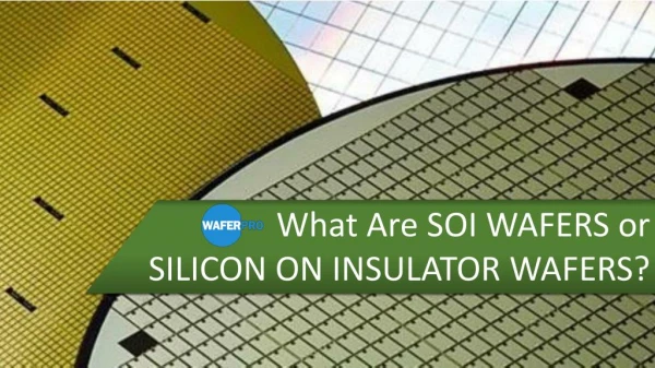
Silicon on Insulator Advanced Electronic Devices Karthik Swaminathan
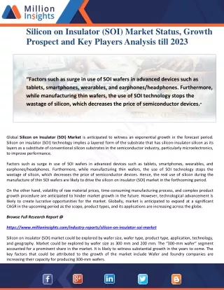
Reasons for SOI • Replacement for SOS • Need to extend Moore’s Law • Commercial Availability of SOI wafers
Advantages of SOI • Reduced Source and Drain to Substrate Capacitance. • Absence of Latchup. • Lower Passive current. • Denser Layout Low cost.
SOI Wafer Fabrication • Bond and Etch Back • SIMOX (Separation by IMplantation Of oXygen) • SIMON(Separation by IMplantation Of Nitrogen)
Oxygen BOX heat SIMOX SIMOX silicon
Fully Depleted (FD) SOI • This is what you expect. • FDSOI MOSFET • Depleted channel. http://www.soisic.com/SOI_keys_benefits.htm
Partially Depleted (PD) SOI • What if active Si layer is thick ? • Body in channel floating Floating body effect. http://www.soisic.com/SOI_keys_benefits.htm
Novel SOI Devices • Dual gate SOI. • SOI Single electron transistors.
Double-Gate SOI MOSFET • ITRS roadmap – dual gate SOI at 15nm. • Thick gate oxide to ensure equal thickness on both sides. IEEE Tran on Elec. Dev. 50,3,March 2003,Ultimately Thin Double-Gate SOI MOSFETs Thomas Ernst et al.
Issues – Negative resist for EBL • PMMA resist is a good positive resist for EBL. • Do we have a good negative EBL resist high resolution. • NO alternate techniques.
Negative Resist – SOI ? • EBL. • Plasma oxidation. • Etching of amorphous silicon. • BOX removal.
Negative resist – silicon ? • EBL • Plasma oxidation • Electron cyclotron resonance chlorine etching of silicon.
Pattern dependent oxidation • Thermal gate oxidation. • Oxygen diffuses through the BOX and reaches the pattern edges which are oxidized. • Stresses due to volume change prevent oxidation of the island.
Summary • Future devices will involve SOI. • SOI provides certain benefits over bulk CMOS for smaller gate lengths. • SOI SETs may become a promising technology in the future.