Download
1 / 18
180 likes | 366 Vues
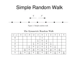
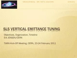
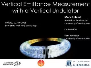
Vertical emittance minimization at the SLS through systematic and random-walk optimization. CLIC meeting, CERN 20.04.2012 M. Aiba, M. B öge, N. Milas, A. Streun, PSI. Introduction. Vertical emittance minimization is motivated by: increase of brightness and transverse coherence

E N D
Vertical emittance minimization at the SLS through systematic and random-walk optimization CLIC meeting, CERN 20.04.2012 M. Aiba, M. Böge, N. Milas, A. Streun, PSI
Introduction • Vertical emittance minimization is motivated by: • increase of brightness and transverse coherence • operational margin for small gap insertion device (possibly even smaller undulator gap) • TIARA WP6 SVET (SLS Vertical Emittance Tuning) • Collaboration: CERN-INFN-PSI+Maxlab • Establish VET means at SLS, for CLIC DR and SuperB → Fine corrections of betatron coupling and hy, and maintaining small emittance during operation • Beam size monitor R&D → NM’s talk • Intra Bunch Scattering studies
Swiss Light Source Swiss Light Source • 3rd generation light source • 18(+2) beam lines • 2.4 GeV, 400 mA (top-up) • C~288 m SLS
SLS vertical emittance • What was expected and what is achieved • Achieved much better than expected, thanks to • 30 more skew quads installed (6 skew quads initially) • Better alignment on girder than expected • Girder realignment in 2011 • Elaborated model based corrections • Random-walk optimization Emittance ratio ≡ ev/eh eh~ 5 nm (Insertion devices off) 1.8 pm in March 2011 Application of these methods achieved 0.9 pm!
Key component 1 • Magnet girder • BBGA initially planned (see Backup slide) • Switch to BAGA (later slides), more robust approach
Girder realignmentMotivation and approach Girder discontinuity estimation from “corrector pattern” • BAGA (Beam Assisted Girder Alignment) • Remotely align girders based on survey data • Confirm the result online with beam and fast orbit feedback running
Girder realignment result Result for all sectors Result for Sector 1 • BAGA resulted in: • Gaussian like corrector kick distribution • About half corrector kick • About half dispersive skew correction • Similar non-dispersive skew correction (Qaud rotation dominant?)
Model based correction 2 * ORM * Contribution of BPM tilts subtracted
Random walk optimization • Limitations in model based corrections… • Beam measurement errors • Model deficiencies • Apply multi-variable optimization • Random-walk would be the best algorithm • Model independent correction • The curse of dimensionality is avoided (#Knobs=12/24/36) • The optimum solution is within easy “walking-distance” after systematic correction • Minimal effort to implement • Potential of online optimization, i.e. keeping small emittance during the operation • NB: the optimization needs a target function, which is the measured vertical beam size in our case RAndom Coupling Correction (RACC) ~ Luck (in Japanese pronunciation…)
Configure the parameters of RWO Measure target function, f0 Generate random corrections (RC) Add RC to the present correction variables Measure target function, f f<f0 f≥f0 Update f0=f Remove RC Reconfigure RWO if necessary How it works Typical successful step (Figure from first test) Flowchart
Corrected vertical dispersion MD on 6th Dec. 2011 Beam size measurement during MD ND skew Q currents during RWO (plotted 4 out of 24) • First dedicated MD after BAGA • hv~1.3 mm rms with model based correction! • ev~1.2 pm at the end of model based correction • ev~0.9±0.4 pm with RWO in addition! (Only ND skew quads optimized) • Better coupling correction with RWO was confirmed with ORM before and after
Model deficiencies? • What limits the model based correction? • Step size of RWO was determined from the continuation of model based correction after it converged → Fluctuation of correction due to measurement error DKL~10-5m-1rms → Step size chosen in a range of DKL=0.5~2×10⁻⁵m-1 • However, RWO arrived at DKL=7×10⁻⁵m-1rms • BPM and corrector tilts may be the sources Simulation showed residual tilts of a few mrad already explain this
Summary • Ultra low vertical emittance of 0.9 pm is achieved at the SLS ! • BAGA + Model based corrections + RWO • RWO • Successfully demonstrated, a good performance booster • Potential applications: • Beam lifetime of the SLS, SwissFEL undulator BBA etc. • Online optimization Maintain small emittance during operation in CLIC DR and SuperB