Download
1 / 2
80 likes | 1.04k Vues
Plunger Lift Reference Guide. Base Mgmt. By Pass Non-Conventional. High Speed Non-Conventional. By Pass. Hollow center. By Pass with Pad. Ports. Pacemaker. Name: Ring Frictionless By Pass Manufacturer: PCS. Name: Center By Pass Manufacturer: PCS. Example Wells: Fazekas 2-17

E N D
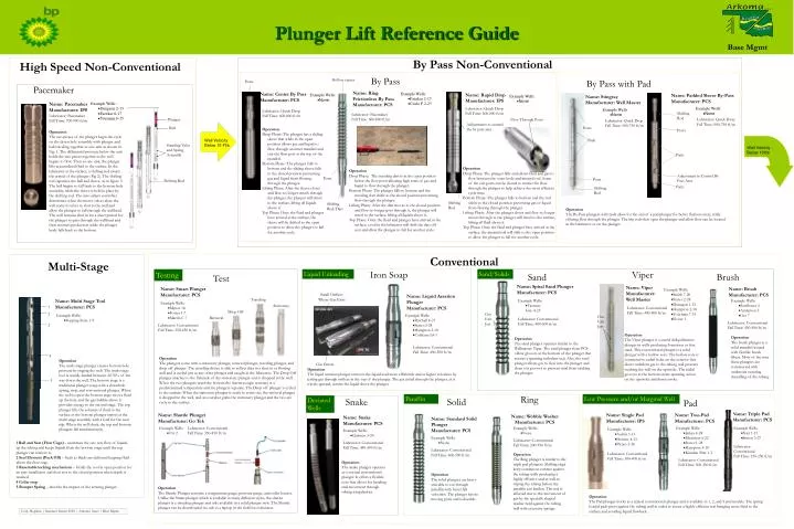
Plunger Lift Reference Guide Base Mgmt By Pass Non-Conventional High Speed Non-Conventional By Pass Hollow center By Pass with Pad Ports Pacemaker Name: Ring Frictionless By Pass Manufacturer: PCS Name: Center By Pass Manufacturer: PCS • Example Wells: • Fazekas 2-17 • Circle F 2-25 Name: Rapid Drop Manufacturer: IPS • Example Wells: • None Name: Padded Sleeve By-Pass Manufacturer: PCS • Example Wells: • None Name: Stingray Manufacturer: Well Master Name: Pacemaker Manufacturer: IPS Operation The two pieces of the plunger begin the cycle on the down hole assembly with plunger and ball traveling together as one unit as shown in Fig. 1. The differential pressure below the unit holds the two pieces together as the well begins to flow. Then as one unit, the plunger lifts accumulated fluid to the surface. In the lubricator at the surface, a shifting rod awaits the arrival of the plunger (Fig 2). The shifting rod separates the ball and sleeve, as in figure 3. The ball begins to fall back to the bottom-hole assembly, while the sleeve is held in place by the shifting rod. The auto-adjust controller determines when the motor valves close the well control valves to shut in the well and allow the plunger to fall through the wellhead. The well remains shut in for a short period for the plunger to pass through the wellhead and then resumes production while the plunger body falls back to the bottom. • Example Wells: • Dungeon 2-13 • Fazekas 6-17 • Yourman 6-15 Lubricator: Quick Drop Fall Time: 600-800 ft/m • Example Wells: • None • Example Wells: • None Lubricator: Quick Drop Fall Time: 600-800 ft/m Shifting Rod Lubricator: Pacemaker Fall Time: 600-800 ft/m Lubricator: Pacemaker Fall Time: 700-900 ft/m Plunger Flow Through Ports Lubricator: Quick Drop Fall Time: 500-750 ft/m Lubricator: Quick Drop Fall Time: 500-750 ft/m Adjustments to control the by pass area Ball Ports Operation Drop Phase: The plunger has a sliding sleeve that while in the open position allows gas and liquid to flow through an inner mandrel and exit the flow port at the top of the mandrel. Bottom Phase: The plunger falls to bottom and the sliding sleeve falls to the closed position preventing gas and liquid from flowing through the plunger. Lifting Phase: After the sleeve closes and flow no longer travels through the plunger, the plunger will travel to the surface, lifting all liquids above it. Top Phase: Once the fluid and plunger have arrived at the surface, the sleeve will be shifted to the open position to allow the plunger to fall for another cycle. Ports Well Velocity Below 15 Ft/s Pads Standing Valve and Spring Assembly Well Velocity Below 10ft/s Pads Operation Drop Phase: The plunger falls and allows fluid and gas to flow between the outer body and internal rod. Some of the exit ports can be closed to restrict the flow through the plunger to help achieve the most efficient cycle time. Bottom Phase: The plunger falls to bottom and the rod shifts to the closed position preventing gas or liquid from flowing through the plunger. Lifting Phase: After the plunger closes and flow no longer moves through it, the plunger will travel to the surface, lifting all fluid above it. Top Phase: Once the fluid and plunger have arrived at the surface, the internal rod will shift to the open position to allow the plunger to fall for another cycle. Operation Drop Phase: The traveling dart is in the open position below the flow ports allowing high rates of gas and liquid to flow through the plunger. Bottom Phase: The plunger falls to bottom and the traveling dart shifts to the closed position preventing flow through the plunger. Lifting Phase: After the dart moves to the closed position and flow no longer goes through it, the plunger will travel to the surface, lifting all liquids above it. Top Phase: Once the fluid and plunger have arrived at the surface, a rod in the lubricator will shift the dart off seat and allow the plunger to fall for another cycle. Adjustment to Control By Pass Area Ports Ports Shifting Rod Pads Shifting Rod Shifting Rod Shifting Rod/Dart Operation The By-Pass plungers with pads allow for the seal of a pad plunger for better fluid recovery, while offering flow through the plunger. The trip rods that open the plunger and allow flow can be located in the lubricator or on the plunger. Conventional Multi-Stage Iron Soap Viper Testing Liquid Unloading Sand/Solids Sand Brush Test Name: Spiral Sand Plunger Manufacturer: PCS Name: Viper Manufacturer: Well Master Name: Smart Plunger Manufacturer: PCS Name: Brush Manufacturer: PCS • Example Wells: • Smith 7-20 • State c2-28 • Dunagan 1-13 • Hampton 2-18 • Yourman 7-15 • Foster 1 Small Orifices Where Gas Exits Name: Liquid Aeration Plunger Manufacturer: PCS Traveling Name: Multi Stage Tool Manufacturer: PCS • Example Wells: • Varnum, Guy 4-25 • Example Wells: • Sunflower 3 • Anderson 3 • Orr 7 • Example Wells: • Myton 18 • Foster 1-7 • Martin C 7 Stationary 1 Lubricator: Conventional Fall Time: 400-500 ft/m Drop Off 2 Gas Exit Jets • Example Wells: • Topping State 1-9 • Example Wells: • Paschall 4-21 • State c3-28 • Hampton 2-18 • Coblentz b3-1 Gas Exit Jets Retrieval Lubricator: Conventional Fall Time: 400-500 ft/m Lubricator: Conventional Fall Time: 450-500 ft/m 3 Lubricator: Conventional Fall Time: 350-450 ft/m Operation The Viper plunger is a useful deliquification plunger in wells producing formation or frac sand. This conventional plunger is a solid plunger with a hollow core. The hollow core is connected to radial holes on the exterior that direct turbulent gas to the tubing wall pressure washing the wall on the upstroke. The radial grooves in the bottom create spinning action on the upstroke and down stroke. Operation The brush plunger is a solid mandrel wound with flexible brush fibers. Most of the time these plungers are constructed with undercuts ensuring descalling of the tubing. Operation The sand plunger operates similar to the Wellmaster Viper. The sand plunger from PCS offers grooves at the bottom of the plunger that creates a spinning turbulent seal. Also, the sand plunger allows gas to flow into the plunger and clean out grooves to prevent sand from sticking the plunger. Lubricator: Conventional Fall Time: 450-500 ft/m 4 Operation The plungers come with a stationary plunger, retrieval plunger, traveling plunger, and drop off plunger. The traveling device is able to collect data in a shut-in or flowing well and is cycled just as any other plunger and caught in the lubricator. The Drop Off plunger attaches to the fishneck of the stationary plunger and is dropped in the well. When the two plungers reach the bottom the thermocouple activates at a predetermined temperature and the plungers separate. The Drop off plunger is cycled to the surface. When the stationary plunger is ready to come out, the retrieval plunger is dropped in the well, and an overshot grabs the stationary plunger and the two are cycle to the surface. Operation The multi stage plunger creates bottom hole pressure by staging the well. The multi stage tool is usually landed between 40-70% of the way down the well. The bottom stage is a traditional plunger setup with a downhole spring, stop, and conventional plunger. When the well is open the bottom stage moves fluid up the hole and the gas bubble above it provides energy to the second stage. The top plunger lifts the column of fluid to the surface as the bottom plunger arrives at the multi stage assembly with a load for the next trip. When the well shuts, the top and bottom plungers fall simultaneously. Gas Enters Operation The liquid aeration plunger removes the liquid load more efficiently and at higher velocities by jetting gas through orifices in the top of the plunger. The gas jetted through the plunger, as it travels upward, aerates the liquid above the plunger. 5 Ring Paraffin Low Pressure and/or Marginal Well Deviated Wells Snake Solid Pad Name: Triple Pad Manufacturer: PCS Name: Shuttle Plunger Manufacturer: Go Tek Name: Single Pad Manufacturer: IPS Name: Two-Pad Manufacturer: PCS Name: Wobble Washer Manufacturer: PCS Name: Snake Manufacturer: PCS Name: Standard Solid Plunger Manufacturer: PCS • Example Wells: • Orr 2 Lubricator: Conventional Fall Time: 350-450 ft/m • Example Wells: • None • Example Wells: • James 4-24 • Mcalester 6-22 • State c1-28 • Hampton 3-18 • Kinnkin Pate 1-3 • Example Wells: • Nan 1-15 • Simon 3-27 • Example Wells: • Austin 5-13 • Heitner 4-13 • Picaro 2-36 • Example Wells: • Quinton 3-20 • Example Wells: • None Lubricator: Conventional Fall Time: 200-350 ft/m 1 Ball and Seat (Flow Cage) – maintains the one way flow of liquids up the tubing and keeps liquids from the bottom stage until the top plunger can retrieve it. 2 Seal Element (Pack Off) – Seals as fluids are delivered keeping fluid above the flow cage. 3 Resettable locking mechanism – Holds the tool in open position for an easy installation and then sets to the closed position when depth is reached. 4 Collar stop 5 Bumper Spring – absorbs the impact of the arriving plunger. Lubricator: Conventional Fall Time: 450-500 ft/m Lubricator: Conventional Fall Time: 150-250 ft/m Lubricator: Conventional Fall Time: 400-500 ft/m Lubricator: Conventional Fall Time: 300-400 ft/m Operation The Ring plunger is similar to the triple pad plungers. Shifting rings keep continuous contact against the tubing walls producing a highly effective seal as well as wiping the tubing before the paraffin can harden. The seal is affected due to the movement of gas by the specially shaped washer held against the tubing wall with eccentric springs. Lubricator: Conventional Fall Time: 300-350 ft/m Operation The snake plunger operates as a normal conventional plunger. It offers a flexible core that allows for bending and movement through tubing irregularities. Operation The solid plungers are heavy and able to cut through paraffin with faster fall velocities. The plunger has no moving parts and is durable. Operation The Shuttle Plunger contains a temperature gauge, pressure gauge, and collar locator. Unlike the Smart plunger which is available in many different styles, the shuttle plunger is a traveling plunger and only available in a solid plunger style. The Shuttle plunger can be downloaded via usb to a laptop in the field for evaluation. Operation The Pad plunger works as a typical conventional plunger and is available in 1, 2, and 3 pad models. The spring loaded pads press against the tubing wall in order to create a highly efficient seal bringing more fluid to the surface and avoiding liquid flowback. Cody Hopkins | Summer Intern 2010 | Arkoma Asset | Base Mgmt
Plunger Lift Reference Guide Surface Equipment Fazekas #5 Controller / Motor Valve Lubricator Master Valve Flow Line to Sales Cody Hopkins | Summer Intern 2010 | Arkoma Asset | Base Mgmt Base Mgmt Common Plunger Lift Setup In this range for actual production, the recommendation would be to install a high speed non-conventional plunger (i.e. pacemaker). In this range, the recommendation would be to run a bypass style non-conventional plunger At lower flow rates (below 10ft/s), a conventional style of plunger would be recommended Lubricators Bumper Spring Assembly The lubricator is installed on top of the tree or master valve to cushions the plunger upon arrival into the wellhead to prevent damage. The spring inside absorbs the impact of the plunger. The catcher holds the plunger in place and allows for safe removal of the plunger or inspection. All lubricators are available with on or two outlets. • PCS Bumper Spring Features: • Standard Fishing Neck • Tapered body • Spring • -Helps prevent down hole damage due to plunger fall • Mandrel • Standing Valve Cage • - ball and seat are used to hold liquid in the tubing • “No-Go” • -prevent fall through seating nipple • Cups • -sits in the seating nipple • 8. Locking Mechanism • Orifice • - allows flow through the bumper spring assembly PCS Conventional Lubricator IPS Pace Maker Lubricator Pace Maker Setup Conventional Setup Top View Cap Bumper plate Pace Maker text is right side up, indicating it is for use with the pace maker Bumper plate Cap Spring Spring Spring Pace Maker text is upside down Threaded to Remove Plunger Threaded to Remove Plunger Shifting Rod Outlet Outlet Catcher Ledges to hold the spring or shifting rod in the lubricator. Outlet Catcher (once plunger is at the surface, it can be caught by shifting the handle) Catcher In this set-up the shifting rod is inserted into the spring. During the operation the spring and rod will be assembled as shown inside the lubricator. To change from the Pace Maker setup to this conventional setup, the upper portion must be unscrewed and flipped around. The shifting rod also must be pulled out and a second bumper spring ( not pictured) must be placed inside the existing spring. Standing valves