Download
1 / 1
10 likes | 172 Vues
a). b). Q. Q. T S. T S. Q H. R s. R t. T 0. R c. inaccessible. T C. with. Evaporative cooling in ATLAS – present and future Georg Viehhauser for the ATLAS ID collaboration. The ATLAS evaporative cooling system. Radiation damage control. A simple model of thermal stability.

E N D
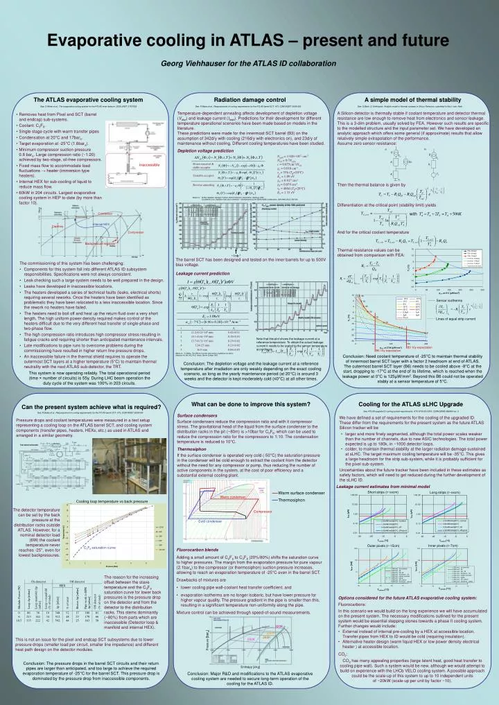
a) b) Q Q TS TS QH Rs Rt T0 Rc inaccessible TC with Evaporative cooling in ATLAS – present and futureGeorg Viehhauser for the ATLAS ID collaboration The ATLAS evaporative cooling system Radiation damage control A simple model of thermal stability See: D.Attree et al., The evaporative cooling system for the ATLAS inner detector, 2008 JINST 3 P07003 See: R.Bates et al., Reassessment of cooling requirements for the ATLAS barrel SCT, ATL-COM-INDET-2009-093 See: G.Beck, G Viehhauser, Analytic model of thermal runaway in Silicon Detectors, submitted to Nucl. Instr. Neth. Temperature-dependent annealing affects development of depletion voltage (Vdep) and leakage current (Ileak). Predictions for their development for different temperature operational scenarios have been made based on models in the literature. These predictions were made for the innermost SCT barrel (B3) on the assumption of 342d/y with cooling (216d/y with electronics on), and 23d/y of maintenance without cooling. Different cooling temperatures have been studied. Depletion voltage prediction A Silicon detector is thermally stable if coolant temperature and detector thermal resistance are low enough to remove heat from electronics and sensor leakage. This is a 3-dim problem, usually solved by FEA. However such results are specific to the modelled structure and the input parameter set. We have developed an analytic approach which offers some general (if approximate) results that allow relatively simple extrapolation of the performance. Assume zero sensor resistance: • Removes heat from Pixel and SCT (barrel and endcap) sub-systems. • Coolant: C3F8. • Single stage cycle with warm transfer pipes • Condensation at 20°C and 17bara. • Target evaporation at -25°C (1.6bara). • Minimum compressor suction pressure 0.8 bara. Large compression ratio (~1:20) achieved by two-stage, oil-free compressors. • Fixed mass flow to accommodate load fluctuations → heater (immersion type heaters). • Internal HEX for sub-cooling of liquid to reduce mass flow. • 60kW in 204 circuits. Largest evaporative cooling system in HEP to-date (by more than factor 10). Neff,0 = 1.026×1012 cm-3 NC0 = 0.7Neff,0 c = 0.075cm-1/NC0 ga = 0.018 cm-1 τa = 55h (TR=20°C) Ea = 1.09 eV gC = 0.017 cm-1 gY= 0.059 cm-1 τY = 480d (TR=20°C) EY = 1.33 eV Then the thermal balance is given by Based on: M.Moll, Radiation Damage in Silicon Particle Detectors, Dissertation, Hamburg 1999. G.Lindström et al., Radiation hard silicon detectors – developments by the RD48 (ROSE) collaboration, NIM A466 (2001) 308-326. Differentiation at the critical point (stability limit) yields Condenser Internal HEX Capillary And for the critical coolant temperature Compressor Backpressure regulator Thermal resistance values can be obtained from comparison with FEA: ~1nb-1 The barrel SCT has been designed and tested on the inner barrels for up to 500V bias voltage. Leakage current prediction • The commissioning of this system has been challenging: • Components for this system fall into different ATLAS ID subsystem responsibilities. Specifications were not always consistent. • Leak checking such a large system needs to be well prepared in the design. • Leaks have developed in inaccessible locations. • The heaters developed a series of technical faults (leaks, electrical shorts) requiring several reworks. Once the heaters have been identified as problematic they have been relocated to a less inaccessible location. Since the rework no heaters have failed. • The heaters need to boil off and heat up the return fluid over a very short length. The high uniform power density required makes control of the heaters difficult due to the very different heat transfer of single-phase and two-phase flow. • The high compression ratio introduces high compressor stress resulting in fatigue cracks and requiring shorter than anticipated maintenance intervals. • Late modifications to pipe runs to overcome problems during the commissioning have resulted in higher return line pressure drops. • An inaccessible failure in the thermal shield requires to operate the outermost SCT layers at a higher temperature (5°C) to maintain thermal neutrality with the next ATLAS sub-detector, the TRT. Sensor isotherms Lines of equal strip current Note that this plot shows the leakage current at a reference temperature. To obtain the actual leakage current it needs to be scaled to the sensor temperature according to B3 10y expectation B6 10y expectation Based on: S.J.Bates, The effects of proton and neutron irradiations on silicon detectors for the LHC, Ph.D. thesis, Darwin College 1993. Conclusion: Need coolant temperature of -25°C to maintain thermal stability of innermost barrel SCT layer with a factor 2 headroom at end of ATLAS. The outermost barrel SCT layer (B6) needs to be cooled above -8°C at the start, dropping to -17°C at the end of its lifetime, which is reached when the leakage power at 0°C is 125μW/mm2. Beyond this B6 could not be operated stably at a sensor temperature of 5°C. Conclusion: The depletion voltage and the leakage current at a reference temperature after irradiation are only weakly depending on the exact cooling scenario, as long as the yearly maintenance period (at 20°C) is around 3 weeks and the detector is kept moderately cold (≤0°C) at all other times. This system is now operating reliably. The total operational period (time × number of circuits) is 55y. During LHC beam operation the duty cycle of the system was 100% in 203 circuits. What can be done to improve this system? Cooling for the ATLAS sLHC Upgrade Can the present system achieve what is required? See: ATLAS upgrade ID cooling system requirements, ATU-SYS-ES-0004, CERN EDMS 986954 ver. 5 See: R.Bates et al., Reassessment of cooling requirements for the ATLAS barrel SCT, ATL-COM-INDET-2009-093 Surface condensers Surface condensers reduce the compression ratio and with it compressor stress. The gravitational head of the liquid from the surface condenser to the distribution racks in the pit (~80m) is >10bar for C3F8, which can be used to reduce the compression ratio for the compressors to 1:10. The condensation temperature is reduced to 10°C. Thermosiphon If the surface condenser is operated very cold (-50°C) the saturation pressure in the condenser will be cold enough to extract the coolant from the detector without the need for any compressor or pump, thus reducing the number of active components in the system, at the cost of poor efficiency and a substantial external cooling plant. We have defined a set of requirements for the cooling of the upgraded ID. These differ from the requirements for the present system as the future ATLAS Silicon tracker will be Pressure drops and coolant temperatures were measured in a test setup representing a cooling loop on the ATLAS barrel SCT, and cooling system components (transfer pipes, heaters, HEXs, etc.) as used in ATLAS and arranged in a similar geometry. • larger and more finely segmented, although the total power scales weaker than the number of channels, due to new ASIC technologies. The total power expected is up to 180k, in ~1000 detector loops. • colder, to maintain thermal stability at the larger radiation damage sustained at sLHC. The target maximum cooling temperature will be -35°C. This gives a large headroom for the strip sub-system, while it is probably sufficient for the pixel sub-system. Uncertainties about the future tracker have been included in these estimates as safety factors, which will need to get reduced during the further development of the sLHC ID. Leakage current estimates from minimal model Short strips (r~xxcm) Long strips (r~xxcm) Warm surface condenser Warm condenser Thermosiphon Cooling loop temperature vs back pressure The detector temperature can be set by the back pressure at the distribution racks outside ATLAS. However, for a nominal detector load (6W) the coolant temperature never reaches -25°, even for lowest backpressures. Compressor Cold condenser Inner pixels (r~7cm) Outer pixels (r~15cm) C3F8 saturation curve • Fluorocarbon blends • Adding a small amount of C2F6 to C3F8 (20%/80%) shifts the saturation curve to higher pressures. The margin from the evaporation pressure for pure vapour (2.1bara) to the compressor (or thermosiphon) suction pressure increases, allowing to reach an evaporation temperature of -25°C even in the barrel SCT. • Drawbacks of mixtures are • lower cooling pipe wall-coolant heat transfer coefficient, and • evaporation isotherms are no longer isobaric, but have lower pressure for higher vapour quality. The pressure gradient in the pipe is smaller than this, resulting in a significant temperature non-uniformity along the pipe. • Mixture control can be achieved through speed-of-sound measurements. The reason for the increasing offset between the stave temperature and the C3F8 saturation curve for lower back pressures is the pressure drop on the detector and from the detector to the distribution racks. This stems dominantly (~80%) from parts which are inaccessible (Detector loop & manifold and internal HEX). Options considered for the future ATLAS evaporative cooling system: Fluorocarbons: In this scenario we would build on the long experience we will have accumulated on the present system. The necessary modifications outlined for the present system would be essential stepping stones towards a phase II cooling system. Further changes would include: 320K • External instead of internal pre-cooling by a HEX at accessible location. Transfer pipes from HEX to ID would be cold (requiring insulation). • Alternative heater design (warm liquid HEX or low power density electrical heater ) at accessible location. 300K 280K This is not an issue for the pixel and endcap SCT subsystems due to lower pressure drops (smaller load per circuit, smaller line impedance) and different heat path design on the detector modules. 250K Pressure [bara] CO2: CO2 has many appealing properties (large latent heat, good heat transfer to cooling pipe wall). Such a system would be new, although we would attempt to build on experience with the LHCb VELO cooling system. A possible approach could be the scale-up of this system to up to 10 independent units of ~20kW (scale-up per unit by factor ~10). Conclusion: The pressure drops in the barrel SCT circuits and their return pipes are larger than anticipated, and too large to achieve the required evaporation temperature of -25°C for the barrel SCT. This pressure drop is dominated by the pressure drop from inaccessible components. Enthalpy [J/kg] Conclusion: Major R&D and modifications to the ATLAS evaporative cooling system are needed to secure long-term operation of the cooling for the ATLAS ID.