Download
1 / 19
190 likes | 595 Vues
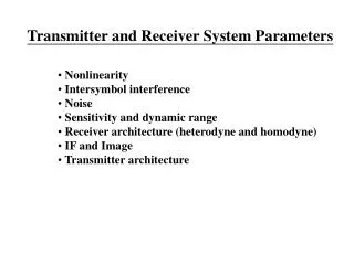
Chapter4 Transmitter and Receiver Applications AM and FM Radios GSM and CDMA TV Transmitters and Receivers Direct Broadcast Satellite ( DBS ) TV. Huseyin Bilgekul Eeng360 Communication Systems I Department of Electrical and Electronic Engineering Eastern Mediterranean University.

E N D
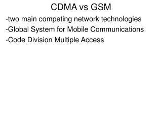
Chapter4 • Transmitter and Receiver Applications • AM and FM Radios • GSM and CDMA • TV Transmitters and Receivers • Direct Broadcast Satellite (DBS) TV Huseyin Bilgekul Eeng360 Communication Systems I Department of Electrical and Electronic Engineering Eastern Mediterranean University
The GSM and CDMA networks. MSC = mobile switching center; BST = base transceiver station; BSC = base station controller.
GSM Mobile Phone Transmitter Receiver
CDMA Cell Phone Mobile Phone Transmitter
DBS-TV footprint and rain regions - 4 dB - 6 dB - 4 dB - 2 dB 150o 120o 90o 60o 30o
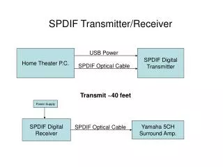
DBS TV Uplink Transmitter QPSK IF amplifier upconverter LPA HPA Multiplexer modulator M MUX 17 GHz uplink antenna ~ ~ Other RF signals RF LO 70 MHz LO Digital multiplexer Reed-Soloman encoder Convolutional encoder MPEG-2 encoder Interleaver MPEG 2 R-S Coder Conv Coder ADC MUX I Analog video and audio signals Other digital signals
DBS TV Receiver 12.2 – 12.7 GHz DBS-TV signal Image rejection BPF 900 - 1400 MHz IF amplifier LNA Mixer Low noise block converter mounted on antenna feed Coaxial cable to set top receiver Local oscillator 11.3 GHz Ku-band antenna 900 - 1400 MHz IF amplifier 70 MHz IF amplifier QPSK demod Baseband amplifier Mixer D Tuned BPF input Select polarization Tuned LO Select transponder Frequency synthesizer Microprocessor Video Inner decoder Outer decoder MPEG-2 decoder Demux DI D/A Audio Analog output to TV set Deinterleaver
DBS TV Receiver Front End Image rejection BPF Mixer LO 11.3 GHz Ku-band antenna LNA 900 - 1400 MHz IF amplifier LNB mounted on antenna feed Coaxial cable to set top receiver Select polarization
DBS TV Receiver IF Section Coaxial cable from antenna and LNB Baseband amplifier 900 - 1400 MHz IF amplifier 70 MHz IF amplifier QPSK demod Mixer D in Tuned BPF F P to select transponder Frequency synthesizer Tuned LO Microprocessor
DBS TV Receiver Baseband Processing Deinterleaver bits CD DI R-SD Inner convolutional decoder Outer R-S decoder Video DeMux MPEG D/A Audio Analog outputs Digital demux MPEG-2 decoder