Download
1 / 37
410 likes | 644 Vues
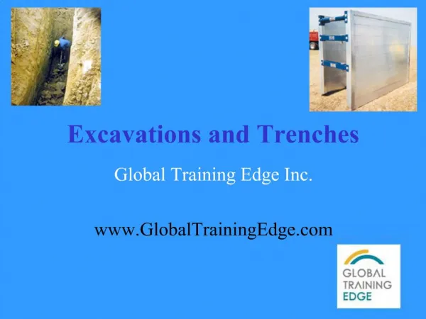
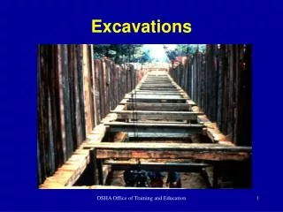
Excavations. 1926 Subpart P EXCAVATION Any man-made cut, cavity, trench, or depression in an earth surface that is formed by earth removal. Cave-ins are much more likely to result in worker fatalities than other excavation-related accidents. TRENCH

E N D
Excavations • 1926 Subpart P • EXCAVATION • Any man-made cut, cavity, trench, or depression in an earth surface that is formed by earth removal. • Cave-ins are much more likely to result in worker fatalities than other excavation-related accidents. • TRENCH • A narrow excavation (in relation to its length) made below the surface of the ground. • The depth of a trench is greater than its width, and the width (measured at the bottom) is not greater than 15 ft (4.6 m).
Soil Mechanics • A number of stresses and deformations can occur in an open cut or trench. • For example, increases or decreases in moisture content can adversely affect the stability of a trench or excavation. • The following diagrams show some of the more frequently identified causes of trench failure.
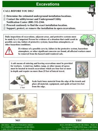
Excavations • 1926.651(b) • Locate underground utilities and installations
Means of Access/Egress • 1926.651(c) • Required in excavations 4 feet or deeper • Provide means of egress • Maximum lateral travel distance in 25 feet
Hazardous Atmospheres • 1926.651(g) • Excavations 4 feet or deeper where hazardous atmospheres can reasonably exist • Oxygen deficiency, oxygen enriched • Toxic gases, flammable vapors • Provide ventilation and/or PPE
Emergency Rescue Equipment • Emergency rescue equipment is required when a hazardous atmosphere exists or can reasonably be expected to exist. • Requirements are as follows: • Respirators must be of the type suitable for the exposure. • Attended (at all times) lifelines must be provided when employees enter bell-bottom pier holes, deep confined spaces, or other similar hazards. • Employees who enter confined spaces must be trained.
Control of Water • 1926.651(h) • PROTECT EMPLOYEES FROM THE ACCUMULATION OF WATER • MONITOR WATER REMOVAL EQUIPMENT
Protection of Employees • 1926.652(a) • Protect employees in the excavation from cave-ins in excavations 5 feet and deeper • Protection could be required at depths less than 5 feet if there is an indication of a potential cave-in, work activities warrant protection, etc. • Not required for excavations made entirely in stable rock
Protection Systems • 1926.652 • Sloping and benching • Shielding, support, or other protective system
Stable Rock • Stable rock is natural solid mineral matter that can be excavated with vertical sides and remain intact while exposed. • It is usually identified by a rock name such as granite or sandstone.
TYPE A SOILS • Examples of Type A cohesive soils are often: clay, silty clay, sandy clay,clay loam. • Compressive forces of 1.5 tsf or greater
TYPE B SOILS • Type B soils are: angular gravel; silt; silt loam; previously disturbed soils unless otherwise classified as Type C • Compressive forces greater than .5 tsf but less than 1.5 tsf
TYPE C SOILS • Type C soils include granular soils such as gravel, sand and loamy sand, submerged soil, soil from which water is freely seeping, and submerged rock that is not stable. • Compressive forces .5 tsf or less
Soil Field Tests • Thumb test • Plasticity • Pocket penatrometer • Torvane shear • Sedimentation
Thumb Penetration Test • ASTM test designation D 2488 • Retrieve a large clump of undisturbed spoil • Attempt to penetrate the soil with the tip of the thumb • Type A soil can be penetrated only with great force • Type B will penetrate to the full length of the thumb nail • Type C will penetrate easily several inches and can be molded by light finger pressur
Plasticity Test • Roll a moist sample of spoil into a ball • Roll the ball out into a 1/8" by 2 " thread • If this can be done, hold it on end • If it remains suspended without tearing the soil is cohesive
Pocket Penetrometer • POCKET PENETROMETER. Penetrometers are direct-reading, spring-operated instruments used to determine the unconfined compressive strength of saturated cohesive soils. • Once pushed into the soil, an indicator sleeve displays the reading. • The instrument is calibrated in either tons per square foot (tsf) or kilograms per square centimeter (kPa). • However, Penetrometers have error rates in the range of ± 20-40%.
Torvane Shear • Select fresh clod or block of undisturbed soil from spoil pile • Cut a smooth surface on the clod • Insert vanes of device into the soil • Retract vanes to show foot imprint • Set indicator at zero • Hold device firmly against soil and twist in clockwise manner until soil fails in shear
Consistency Term Shear Strength, psf Unconfined Compressive Strength, psf Soil Type Very Soft <250 <500 TYPE “C” Soft 250-500 500-1000 Medium 500-1000 1000-2000 TYPE “B” Stiff Stiff 1000-1500 1500-2000 2000-3000 3000-4000 TYPE “A” Very Stiff Hart 2000-4000 >4000 4000-8000 >8000
Sedimentation Test • Flat bottom container at least 7 inches high • Fill glass jar • 5 inches of water on top of soil • 1 1/2 inches of soil • Place lid on jar and shake • Set jar down • Rotate slightly • Larger particles settle out immediately • Wait 30 seconds • Mark jar • Silt after several minutes • Fine clays in an hour • Make second mark
Sloping Options • NO STEEPER THAN 1 1/2 HORIZONTAL TO 1 VERTICAL (34 DEGREES) • OSHA TABULATED DATA (SOIL CLASSIFICATIONS) • OTHER TABULATED DATA • REGISTERED PROFESSIONAL ENGINEER DESIGN
Slopes for Types of Soil • Stable Rock (Vertical) 90 degrees • TYPE A - (3/4 Horiz. TO 1 Deep) (53 degrees) • TYPE B - (1 Horiz. TO 1 Vertical)(45 degrees) • TYPE C - (1 1/2 Horiz. TO 1 Deep)(34 degrees)
Shoring • Provision of a support system for trench faces used to prevent movement of soil, underground utilities, roadways, and foundations. • Shoring or shielding is used when the location or depth of the cut makes sloping back to the maximum allowable slope impractical.
Types of Shoring • There are two basic types of shoring, timber and aluminum hydraulic • Shoring systems consist of posts, wales, struts, and sheeting.
Hydraulic Shoring • Hydraulic shoring provides a critical safety advantage over timber shoring because workers do not have to enter the trench to install or remove hydraulic shoring.
Hydraulic Shoring • Hydraulic shoring provides a critical safety advantage over timber shoring because workers do not have to enter the trench to install or remove hydraulic shoring. • Other advantages of most hydraulic systems are that they: • are light enough to be installed by one worker; • are gauge-regulated to ensure even distribution of pressure along the trench line; • can be adapted easily to various trench depths and widths.
Installing/Removing Shoring • All shoring should be installed from the top down and removed from the bottom up • Hydraulic shoring should be checked at least once per shift for leaking hoses and/or cylinders, broken connections, cracked nipples, bent bases, and any other damaged or defective parts
Shielding • Trench boxes are different from shoring because, instead of shoring up or otherwise supporting the trench face, they are intended primarily to protect workers from cave-ins and similar incidents. • The space between the trench boxes and the excavation side are backfilled to prevent lateral movement of the box.
Trench Boxes • The box should extend at least 18 in above the surrounding area if there is sloping toward excavation. • This can be accomplished by providing a benched area adjacent to the box. • Earth excavation to a depth of 2 ft below the shield is permitted, but only if the shield is designed to resist the forces
Trench Boxes • The box should extend at least 18 in above the surrounding area if there is sloping toward excavation. • This can be accomplished by providing a benched area adjacent to the box. • Earth excavation to a depth of 2 ft below the shield is permitted, but only if the shield is designed to resist the forces
Spoil Pile • There is also a hazard from excavated material and equipment outside of the excavation falling or rolling down into the trench. • Temporary spoil must be placed no closer than 2 ft from the surface edge of the excavation
Materials and Equipment • Employees must also be protected from excavated materials or equipment that could pose a hazard by falling or rolling into the excavation • This is achieved by placing and keeping materials and equipment at least 2 feet back from the edge of the excavation.
Competent Person • Employers are required to have a competent person on site when trenching and excavation work is in progress. • This person should be knowledgeable of the cave-in hazards and have sufficient authority to act when necessary. • The designated competent person should have and be able to demonstrate the following: • Training, experience, and knowledge of: - soil analysis, - use of protective systems • Ability to detect: - conditions that could result in cave-ins, - failures in protective systems, -hazardous atmospheres, and - other hazard • Authority to take prompt corrective measures
Inspections • Daily inspections of the excavation, adjacent areas and protective systems should be made by a competent person. • The inspections should be made at the start of the work shift and as deemed necessary throughout the shift.
Inspection Frequency • The following guide specifies the frequency and conditions requiring inspections: • Daily and before the start of each shift. • As dictated by the work being done in the trench. • After every rain storm. • After other events that could increase hazards, e.g., snowstorm, windstorm, thaw,earthquake, etc. • When fissures, tension cracks, sloughing, undercutting, water seepage, bulging at the bottom, or other similar conditions occur. • When there is a change in the size, location, or placement of the spoil pile. • When there is any indication of change or movement in adjacent structures.