Download
1 / 36
370 likes | 492 Vues
“ Optical interference corresponds to the interaction of two or more light waves, yielding a resultant irradiance that may deviate from the sum of the component irradiances. ".

E N D
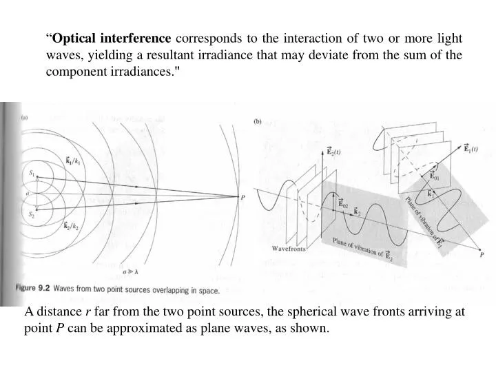
“Optical interference corresponds to the interaction of two or more light waves, yielding a resultant irradiance that may deviate from the sum of the component irradiances." A distance r far from the two point sources, the spherical wave fronts arriving at point P can be approximated as plane waves, as shown.
Consider now linearly polarized plane waves arriving at point P (first slide). The two waves can be described in the usual manner: A point P, the irradiance is given by since the medium doesn’t change. The last term, I12, is referred to as the interference term, it can be evaluated as follows:
Consider now the effect of time averaging: This is the Interference Term Phase Difference Contains the combined path length and phase angle difference. Note that Thus, the resultant wave at point P in this case can be linearly, circularly, or elliptically polarized, but the total flux density (irradiance) won’t change.
Consider the most common situation: Total Constructive Interference There is still constructive interference when 0 < cos < 1 and leads to I1 + I2 < I < Imax . For 0 > cos > -1 this leads to destructive interference. When cos = 1, = , 3, 5, ... Total Destructive Interference, which leads to
Interference of Spherical E-M Waves Note that the Eq. also holds for spherical waves in which in which r1 and r2 are radii of the spherical waves overlapping at P. The phase shift in this case is = k(r1 – r2) + (1-2). Consider 1 = 2 , then r1 – r2 = 2m/k = m (max) for m = 0, 1, 2, … and r1 – r2 = m/k = m/2 (min) for m = 0, 1, 3, … These conditions define hyperbolas in the 2D x-y plane or hyperboloids of revolution in 3D (See Fig. 9.3 as previously shown).
Young’s two slit experiment in which and the two sources are coherent.
Geometry of Young’s Slit Experiment A determination of conditions for constructive interference and appearance of bright fringes: OPD = r1 – r2 = m m Assume that a << s and y << s, i.e., a small angle approx. OPD = Optical Path Length Difference and m = 0, 1, 2, 3… for maxima (bright fringes) Red fringes have a larger spacing and are broader on the screen than blue fringes.
for two overlapping spherical waves. Detector Coherent Source Laser A path length difference of one wave-length corresponds to m = 1 and the first order maximum, on both sides of the central maximum (m = 0).
Ideal irradiance (intensity) vs distance curve. The fringe separation y 1/a. Notice how the width and spacing of the intensity distribution depend on .
s Other wave-front splitting interferometers: Fresnel’s Double Mirror Cylindrical wavefront and the law of reflection gives: Difference in OPL = r1 – r2 = m s = distance between the plane containing S1 and S2 and the screen, just as in the Young’s Experiment.
Fresnel’s Double Prism a = 2d(n-1) where is the prism angle. s is the distance between the source (virtual coherent sources) and the screen, as shown in (a). a
Flat dielectric or metal mirror. Cylindrical wavefront coming from the source at S. Note that at glancing incidence, i 90, the amplitude reflection coef. = -1 which yields a phase shift of = = k(r1-r2) Therefore, Note the spatial shift in the fringe pattern.
Dielectric Films – Double beam interference Creation of fringe pattern from two reflected beams with fields E1r and E2r; ignore higher order beams for now. This is also referred to as an amplitude splitting device. The beams with fields E1r and E2r are considered as coming from two coherent virtual sources behind the film. nf d n1 n1
Let n1 = n2 = n (film is in a single medium) n < nf (e.g., soap film in Air) n > nf (e.g. Air film between sheets of glass) In either case, there will be a relative phase shift of upon reflection. For incident angles up to ~30 (see Fig. 4.44), regardless of [E0r] or [E0r]|| we can expect that = for the two reflected beams. Consider again the rope analogy: Glass (n = 1.5) Air (n = 1) = 0 = 0 Air (n = 1) Glass (n = 1.5) = = 0
Note that this is for the case of maxima in reflected light, but also minima in the transmitted light. The case for minima in reflected light and maxima in transmitted light is as follows: Note that if n1 > nf > n2 or n1 < nf < n2, the - phase shift would not be present.
For an extended source, light will reach the lens from various directions, and the fringe pattern will spread out over a larger area of the film. If the lens used to focus the rays has a small aperture, fringes will appear on a small portion of the film. Only the rays leaving the point source that are reflected directly into the lens will be seen.
Fig. 9.21 Circular Haidinger fringes centered on the lens axis
Optical thickness nfd can also be made to vary instead of i. Consider a wedge-shaped film, as in the previous slide: x d Where x is the horizontal spacing between fringes and dm is the film thickness at various maxima. Note that this is an odd multiple of a quarter wavelength, f/4 and 2 f/4 = f/2 2 / f = + (reflection) 2
Consider the example of Newton’s rings: A lens is placed on an optically flat surface, as shown in Fig. 9-23. The geometry shows mth-order interference max. occurs when Bright ring: Dark ring: Beam splitter Glass
Mirror Interferometers are used to enable two beam interference Michelson Interferometer (see next slide) 1) Silvered surface of beam-splitter (BS) is towards right side (back side). 2) Beam which is reflected by M2 passes through glass of BS three times. 3) Beam which is reflected by M1 passes through glass of BS once. We need to insert “compensator plate” C in arm OM1. Exact Duplicate of BS without the silver coating. Therefore, the difference in OPL is actual path length difference. 4) An additional phase term is present in the OM2 arm, due to an internal reflection in the BS, whereas the OM1 wave has an external reflection at the BS. Therefore 2dcosm = m0 Conditions for destructive interference. m = 0, 1, 2,…, d is the optical path length difference between the mirrors, and m is the inclination angle for a given order m. Note that 2dcosm is the OPD between the two beams (rays).
Fig. 9.25 A conceptual rearrangement of the Michelson interferometer.
Consider a ring for a fixed order m and the diagram of the next slide: As M2 moves towards M1’, d decreases cos m increases m decreases Rings shrink towards center of screen in order to preserve the relation that 2dcosm = m0. One order disappears when d= -0/2. Very precise changes in length are made by counting the number of fringes that disappear. Example: Consider a yellow light source with = 589 nm. When M2 is moved 1 cm, the number of fringes which shrink through the center point is A central dark fringe for m = 0 is represented by 2d = m00 For d fixed (d = const.) successive dark fringes are given by the following relations on the next slide:
p = 5 4 3 2 1 0 (0= 0) Dark Fringes: front view with eyes. y x y S1’ S1’’ S1’’’ 1 2 3 4 S1’’’’ z S1’’’’’ x Dark fringes with angle p from several virtual sources. Side view to give partial 3D visualization.
For d fixed (d = const.) successive dark fringes are given by (see previous slide for labeling of pth fringe) which is the inclination angle of the pth fringe.
Multiple Beam Interference: Arising from multiple internal reflections in a film Difference in OPL between adjacent rays is given by = 2nf dcost . Need to consider various products of amplitude reflection coef: r (1st surface) and r’ (2nd surface), and amplitude transmission coef: t (1st surface) and t’ (2nd surface). Need to find expressions for E1r, E2r, E3r, which are Similarly, the transmitted wave fields are given by:
Time-Reversal Invariance: Important principle in Optics If a process occurs, the reverse can also occur with reflection and refraction, as in the figure below. The time reversal of (a) below gives (b), but (b) in forward time must actually give (c). Self consistency between (b) and (c) requires that Called Stokes Relations These are useful for relating amplitude transmission and reflection coefficients between opposites sides of dielectric films.
Regarding the figure with multiple beams, we can now sum the amplitudes. Assume case (i) in which = m (i.e., difference in OPL between adjacent beams is an integral number of ). For case (ii) = (m + ½) and signs alternate due to an extra ½ in the OPL. Case (i) in which = m Case (ii) = (m + ½)
Case (ii) = (m + ½) Consider now a more general approach involving an arbitrary phase = k0 in which 0 2. A complex representation is necessary. The reflected fields at point P can be described by
The addition of the complex fields can be described and visualized using a phasor diagram: The addition of the complex fields can be accomplished with a similar geometric series, as before: Thus, we reduce to the case of two-beam interference when the reflectance is very small and the leading terms of the first two beams become dominant.
The transmitted fields can also be handled with the same complex method: when there is no absorption or loss of energy. Note that = 2m gives (It)max = Iiand (Ir)min = 0 since sin2(/2) = 0; Likewise, when = (2m + 1) (It)min and (Ir)max since sin2(/2) = 1
This is the identical condition obtained for only two beams (two reflected waves). It is therefore also the same condition for a maximum in the reflected intensity for multiple beams. Define the coefficient of finesse F as follows: This is the Airy Function, which is shown in the next slide for the transmittance.
As r 1, It/Ii is very small, except within sharp spikes at = 2m. Notice that when r2 is small, Ir/Ii approaches sin2/2 as previous mentioned. This reduces to the two beam case: I = 4I0cos2/2 with =k0(r1-r2). The difference is due to an added = due to reflection in the case of dielectric films which cause the cosine to become a sine. This is similar to the case for Lloyds mirror. Note also that multiple beam interference results in a redistribution of the energy density in comparison to the two-beam case, resulting in sharp peaks or dips for r large.