Download
1 / 38
380 likes | 549 Vues
Heating and Cooling. Coordinator: Karel Kabele, kabele@fsv.cvut.cz , CTU in Prague Contributors: Eric Willems , Erwin Roijen , Peter Op 't Veld , P.OpTVeld@chri.nl

E N D
Coordinator: • Karel Kabele, kabele@fsv.cvut.cz, CTU in Prague • Contributors: • EricWillems, Erwin Roijen, Peter Op 't Veld, P.OpTVeld@chri.nl • Camilla Brunsgaard, cbru@create.aau.dk & Mary-Ann Knudstrup, mak@create.aau.dk, Aalborg University, Per Kvols Heiselberg, ph@civil.aau.dk, Tine S. Larsen, Olena K. Larsen, Rasmus Lund Jensen (AAU) • ArturasKaklauskas, Arturas.kaklauskas@st.vgtu.lt, AudriusBanaitis, Audrius.banaitis@vgtu.lt , Vilnius Geniminas Technical University (VGTU) • Marco Perino, marco.perino@polito.it, Gianvi Fracastoro, Stefano Corgnati, Valentina Serra (POLITO) • Werner Stutterecker, werner.stutterecker@fh-burgenland.at, (FH-B) • MattheosSantamouris, msantam@phys.uoa.gr, Margarita Asimakopoulos, Marina Laskari, marlaskari@googlemail.com, (NKUA) • Zoltan Magyar, zmagyar@invitel.hu, Mihaly Baumann, AnikoVigh, idesedu.pte@gmail.com (PTE) • Manuela Almeida, malmeida@civil.uminho.pt, Sandra Silva, sms@civil.uminho.pt, Ricardo Mateus, ricardomateus@civil.uminho.pt, University of Minho (UMINHO) • PiotrBartkiewicz, piotr.bartkiewicz@is.pw.edu.pl, PiotrNarowski, piotr.narowski@is.pw.edu.pl (WUT) • Matthias Haase, matthias.Haase@sintef.no, (NTNU) • Karel Kabele, kabele@fsv.cvut.cz, Pavla Dvořáková, pavla.dvorakova@fsv.cvut.cz, (CTU – FCE)
LECTURE 3 ActiveSpaceheating and cooling
Heat emitters (radiators, convectors, tubular, radiant heating (stripes, panels), dark and light infrared radiant pipes, stoves).
Heating equipment • Heat source - heat transfer medium - heat emitter • Classification of the systems • local • floor • central • district
Convectors Natural Fan-convectors Floor Wall
Water content radiator today Heat insulation (old buildings) Heat insulation standard 1995 (new buildings) Heat insulation Standard 2000 Control limits Large mass = heating unresponsive low mass = responsive heating Mass = storage Responsive heating control important to make use of solar gains G radiator G Panel radiator P Steel radiator S
* radiator temperature, 200C room temperature Convection share Radiation share Single panel radiator, without convector Double panel radiator, with three convectors Finned tube convector Radiator (modular) Thermal output
Off-peak storage • Static • Dynamic • Convector • Radiator
Air flow patterns prof.Ing.Karel Kabele,CSc.
Radiant panels • Low temperature • heaters max 110 °C (water, steam, el.power) • High temperature • dark - about 350°C - radiant tube heating system (gas) • light - about 800 °C - flameless surface gas combustion
Heat emitters • Design principles • Heating output • Location • Covering - furniture • Connection to the pipe system • Type
95% 110% 87% 100% 100% 100% 90% 85% Heatemitters design • Covering = changes in the output • Connection to the piping system
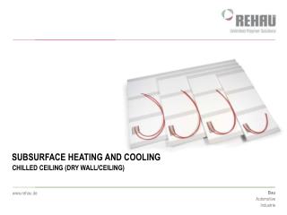
Low-temperature radiant heatingHigh-temperature radiant cooling • Underfloor, wall and/or ceiling heating/cooling • Embededsurfaces • TABS • Snowmeltsystems
Low - temperature radiant heating floor, wall and/or ceiling with embedded pipes or el.wires in concrete slab Temperature distribution Radiators Underfloor heating Ideal temperature Ideal temperature Radiators Underfloor heating 125BEE1_2008/2009 prof.Ing.Karel Kabele,CSc.
Radiant heating/cooling • Output • Limited surface temperature limited output cca 100 W.m-2 • Energy savings • Lower air temperature lower heat losses • Control • Low temperature difference autocontrol effect
Underfloor heating • History
Low/high - temperature radiant heating/cooling • Floor structure Insulating strip between wall and flooring Finished flooring Concrete slab min 65mm Reinforcement Pipes Thermal insulation 20-80mm Supporting floor structure Humidity seal
Underfloor heating - structure TYP B TYP A TYP C
Low - temperature radiant heating • Technical solution • Pipe layout
Wall heating • Embeddedpipes - innerwallside • Highersurfacetemperature on bothsides • Furniture layout • Roomswithgiven use ofspace: swimming pools, entrance areas, corridors • not possible or desirable to use conventional heating surfaces: prisons, hospitals,… • Possibility to use thesystemforcooling
Wall heating - Design process • determination of the areas, applicable to this type of heating; • determine the desired maximum surface temperature; • calculate the heat loss room analogy for underfloor heating without losing the wall with wall heating; • verification of the achievable performance of surfaces and temperature • compared to heat loss, or draft supplementary heating surfaces. • select the type of wall heating, wet or dry system, pipe or capillaries; • design spacing and temperature parameters of heat transfer fluid; • hydraulic calculation.
Wall heating - temperatures • Fromthe point ofthermalcomfortitislikeradiatorsheating • Maximum surfacetemperature 35 - 50 °C according to localconditions. • For surface temperatures above 42 ° C can be painful contact. • size of losses to the outside, impact on the neighboring room • Some manufacturers recommend and design system for the surface temperature of 35 ° C
Technicalsolution A – pipesdiameter 10-14 mm • Wet • Dry B – capillarymats Pipesdiameter 6 mm , rozteč 30-50 mm • Wet
Thermally Activated Building Structures(TABS) • With or without phase change material • Cooling capacity can limit the use of system • Control of room conditions?
Thermalactivation of buildingstructure (TABS) - Nationaltechnicallibrary(Prague) foto: Václav Nývlt, Technet.cz
„Floor“structure Ice50 mm Concrete240 mm Cooling-16/-12°C; 160 W/m2 EPS 250 mm Concrete250 mm
„Floor“structurewithheatingsystem Ice50 mm Concrete240 mm Cooling-16/-12°C 160 W/m2 EPS 250 mm Concrete250 mm Heating 10/8 °C; cca 10 W/m2
Heating of outdoor surfaces Snowmeltsystem Pipe spacing 15-50cm Temperature 50-80°C Use ofantifreeze Thermaloutput according to theamoutofsnow and outdoortemperature Largethermalinertia Mechanicalresistance
Air heating/cooling systems – circulating, ventilating. Integration of heating/cooling systems.