Download
1 / 20
210 likes | 368 Vues
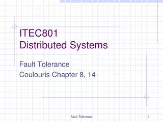
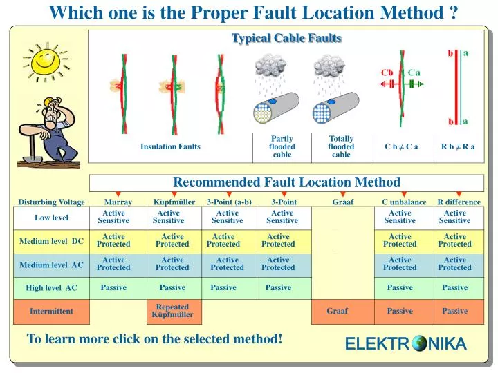
Which one is the Proper Fault Location Method ?. Active Sensitive. Active Sensitive. Active Sensitive. Active Sensitive. Active Sensitive. Active Sensitive. Active Protected. Active Protected. Active Protected. Active Protected. Active Protected. Active Protected.

E N D
Which one is the Proper Fault Location Method ? Active Sensitive Active Sensitive Active Sensitive Active Sensitive Active Sensitive Active Sensitive Active Protected Active Protected Active Protected Active Protected Active Protected Active Protected Active Protected Active Protected Active Protected Active Protected Active Protected Active Protected Passive Passive Passive Passive Passive Passive Repeated Küpfmüller Graaf Passive Passive To learn more click onthe selectedmethod! ELEKTR NIKA
Disturbers The expected disturbing voltage depends on: A.) The function of neighboring pairs in the cable Intermittent disturbing voltages are expected if the neighboring pairs are used forPOTS DC disturbing voltage is expected ifthe neighboring pairs are used only forISDN No disturbing voltage is expected if the neighboring pairs are used only for data transfer B.) The distance to electrical railway High disturbing AC voltage is expected if the cable is very close to the track Low disturbing AC voltage is expected if the cable is fare enough from the track ELEKTR NIKA
Active Bridge Murray Method in Sensitive mode The Murray method consists of 2 measurements: ■ Measurement of disturbing voltages ■ Bridge measurement with strap on the far end ECFL 30 automatically performs the 2 measurements with the help of the remote controlled switch ELC 30 ELEKTR NIKA
Active Bridge Murray Method in Protected mode The Murray method consists of 2 measurements: ■ Measurement of disturbing voltages ■ Bridge measurement with strap on the far end ECFL 30 automatically performs the 2 measurements with the help of the remote controlled switch ELC 30 ELEKTR NIKA
Passive Bridge Murray Method The Murray method requires manual bridge balancing with helipot M. ■the measuring voltage is connected to the ground ■wire a and wire b should be interconnected at the far end The far end can be automatically closed/open with the help of the remote controlled switch ELC 30 ELEKTR NIKA
Active Bridge Küpfmüller Method in Sensitive mode The Küpfmüller method consists of 2 measurements: ■ First measurement with open far end ■ Second measurement with strap on the far end ECFL 30 automatically performs the 2 measurements with the help of the remote controlled switch ELC 30 ELEKTR NIKA
Active Bridge Küpfmüller Method in Protected mode The Küpfmüller method consists of 2 measurements: ■ First measurement with open far end ■ Second measurement with strap on the far end ECFL 30 automatically performs the 2 measurements with the help of the remote controlled switch ELC 30 ELEKTR NIKA
Passive Bridge Küpfmüller Method The Küpfmüller method requires 2 manual bridge balancingswith helipot M. ■ First balancing with open far end ■ Second balancing with strap on the far end The far end can be automatically closed/open with the help of the remote controlled switch ELC 30 ELEKTR NIKA
Active Bridge Repeated Küpfmüller Method That method is a sequence of repeated Küpfmüller measurements consisting of 15 part measurements alternating: ■ 8 measurements with open loop (L) ■ 7 measurements with closed loop(K) The far end is automatically closed/open with the help of the remote controlled switch ELC 30 The Lx/L results are displayed in two columns and a histogram When the sequence is completed ECFL 30 selects the acceptable Lx/L results and calculates the average of the accepted results. The unacceptable results are omitted and marked with asterisks. ELEKTR NIKA
Active Bridge 3-Point (a-b) Method in Sensitive mode Faulty pair FaE Healthy auxiliary wires The 3-Point method consists of 3 measurements: ■ First measurement when the measuring voltage is connected to wire a ■ Second measurement when the measuring voltage is connected to the ground ■ Third measurement when the measuring voltage is connected to wire c ECFL 30 automatically performs the 3 measurements with the help of the remote controlled switch ELC 30 ELEKTR NIKA
Active Bridge 3-Point (a-b) Method in Protected mode Faulty pair FaE Healthy auxiliary wires The 3-Point method consists of 3 measurements: ■ First measurement when the measuring voltage is connected to wire a ■ Second measurement when the measuring voltage is connected to the ground ■ Third measurement when the measuring voltage is connected to wire c ECFL 30 automatically performs the 3 measurements with the help of the remote controlled switch ELC 30 ELEKTR NIKA
Passive Bridge 3-Point (a-b) Method Faulty pair FaE Healthy auxiliary wires The 3-Point method requires 3 manual bridge balancing with helipot M. ■ First balancing when the measuring voltage is connected to wire a ■ Second balancing when the measuring voltage is connected to the ground ■ Third balancing when the measuring voltage is connected to wire c The far end can be automatically closed with the help of the remote controlled switch ELC 30 ELEKTR NIKA
Active Bridge 3-Point Method inSensitive mode The 3-Point method consists of 3 measurements: ■ First measurement when the measuring voltage is connected to wire a ■ Second measurement when the measuring voltage is connected to the ground ■ Third measurement when the measuring voltage is connected to wire c ECFL 30 automatically performs the 3 measurements with the help of the remote controlled switch ELC 30 ELEKTR NIKA
Active Bridge 3-Point Method in Protected mode The 3-Point method consists of 3 measurements: ■ First measurement when the measuring voltage is connected to wire a ■ Second measurement when the measuring voltage is connected to the ground ■ Third measurement when the measuring voltage is connected to wire c ECFL 30 automatically performs the 3 measurements with the help of the remote controlled switch ELC 30 ELEKTR NIKA
Passive Bridge 3-Point Method The 3-Point method requires 3 manual bridge balancings with helipot M. ■ First balancing when the measuring voltage is connected to wire a ■ Second balancing when the measuring voltage is connected to the ground ■ Third balancing when the measuring voltage is connected to wire c The far end can be automatically closed with the help of the remote controlled switch ELC 30 ELEKTR NIKA
Synchronous Graaf Method Recommended: for Fault Location of Totally Flooded Cables The level of disturbing DC currents is usually intermittent. For the sake of proper test result the master and slave instruments perform synchronous current measurements at the cable ends. In this case the current rate ( I1 / I2 ) does not depend on the actual value of disturbing currents. Notice: The current measuring method was invented by Dr Robert Van de Graaf in 1931 ELEKTR NIKA
The Original Graaf Method and its Problems TheTheory was perfect: The result doesn't depend on the actual value of currents But in the practice it was not satisfactory due to the following problems: 1.) The sensitivity and accuracy of available current meters were not enough at that time 2.) The reading of meters was strongly subjective in case of intermitting currents ECFL 30 eliminates all the problems of the original Graaf method: 1.) The features of current meters are much better (Sensitivity:3 uA, Ri:1 Ohm, Accuracy: 0,3%) 2.) The master and slave instruments perform synchronous current measurements at the cable ends. ELEKTR NIKA
Resistance Difference Measurement The active bridge of ECFL 30 is accurate and comfortable The passive bridge of ECFL 30 is disturbing voltage tolerant ECFL 30 provides the following results: Ra, Rb, Rloop, Δ R, % ELEKTR NIKA
Capacitance Unbalance Measurement The active bridge of ECFL 30 is accurate and comfortable The passive bridge of ECFL 30 is disturbing voltage tolerant ELEKTR NIKA