Download
1 / 86
1.06k likes | 2.5k Vues
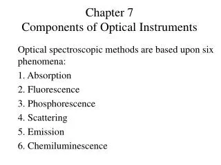
Components of Optical Instruments . Spectroscopic methods are based on either: 1. Absorption 2. Emission 3. Scattering Spectroscopic instruments dependent on any of the above mechanisms encompass common components which can be listed as:. 1. A stable source of radiation

E N D
Spectroscopic methods are based on either: 1. Absorption 2. Emission 3. Scattering Spectroscopic instruments dependent on any of the above mechanisms encompass common components which can be listed as:
1. A stable source of radiation 2. A wavelength selector to choose a single wavelength necessary for a certain absorption, emission or scattering process. 3. A radiation detector (transducer) that can measure absorbed, emitted or scattered radiation. 4. A signal processor that can change the electrical signal (current, voltage, or resistance) to a suitable form like absorbance, fluorescence, etc.
Source Sample Cell Wavelength Selector Detector An Absorption Instrumental Setup Detector Source An Emission or Scattering Instrumental Setup Processor Sample Cell Wavelength Selector Processor
Sources of Radiation A source to be used in a selected range of wavelength should have the following properties: 1. It should generate a beam of radiation covering the wavelength range in which to be used. For example, a source to be used in the visible region should generate light in the whole visible region (340-780 nm). 2. The output of the source should have enough radiant power depending on the technique to be used. 3. The output should be stable with time and fluctuations in the intensity should be minimal.
This necessitates the use of good regulated power supply. Sometimes, a double beam instrument is used to overcome fluctuations in the intensity of the beam with time. In such instruments, the beam from the source is split into two halves one goes to the sample while the other travels through a reference. Any fluctuations in the intensity of the beam traversing the sample will be the same as that traversing the reference at that moment. Subtraction of the reference beam from that of the sample results in excellent correction for fluctuations in the intensity of the beam.
Classifications of Sources There can be several classifications of sources. One classification can be based on where their output is in the electromagnetic spectrum. A second classification can be based on whether the source is a thermal or gas filled lamps, etc. A third method of classification can be based on whether the source is a continuous or a line source. Other classifications do exist but the one which is easier to use is the method which divide sources into either continuous or line sources
Continuous Sources A continuous source is a source, which has an output in a continuum of wavelengths range. An example is deuterium source in the ultraviolet (UV), which has an output in the range from 180-350 nm. Another example is the familiar tungsten lamp covering the range from 340-2500 nm, thus its output extends through the whole visible and near infrared (IR) regions.
Line Sources A line source is a source, which has a line output at definite wavelengths, rather than a range of wavelengths. Hollow cathode and electrodeless discharge lamps are examples of line sources which produce few sharp lines in the UV and visible (Vis). These will be discussed in details in Chapter 9. Another category of line sources is the laser
Lasers The term LASER is an acronym for Light Amplification by Stimulated Emission of Radiation. The first laser was introduced in 1960 and since then too many, highly important applications of lasers in chemistry were described.
Wavelength Selectors • Filters • Prisms • Gratings • Michelson Interferometer
Wavelength Selectors Wavelength selectors are important instrumental components that are used to obtain a certain wavelength or a narrow band of wavelengths. Three types of wavelength selectors can be described: I. Filters Filters are wavelength selectors that usually allow the passage of a band of wavelengths and can be divided into three main categories:
Absorption Filters This type of filters absorbs most incident wavelengths and transmits a band of wavelengths. Sometimes, they are called transmission filters. Absorption filters are cheap and can be as simple as colored glasses or plastics. They transmit a band of wavelengths with an effective bandwidth (the effective band width is the width of the band at half height) in the range from 30-250 nm. Their transmittance is usually low where only about 10-20% of incident beam is transmitted.
Cut-off Filters In this type of filters, transmittance of about 100% is observed for a portion of the visible spectrum, which rapidly decreases to zero over the remainder of the spectrum.
Usually, cut-off filters are not used as wavelength selectors but rather in combination of absorption filters to decrease the bandwidth of the absorption filter or to overcome problems of orders, to be discussed later. Only the combination of the two filters (common area) will be transmitted which has much narrower effective bandwidth than absorption filters alone.
Filters Simple, rugged (no moving parts in general) Relatively inexpensive Can select some broad range of wavelengths Most often used in field instruments simpler instruments instruments dedicated to monitoring a single wavelength range.
Interference Filters These filters are sometimes called Fabry-Perot filters and are dependent on the concept of light interference. An interference filter is composed of a transparent dielectric, like calcium fluoride, sandwiched between two semitransparent metallic films. The array is further sandwiched between two glass plates to protect the filter. The thickness of the dielectric is carefully controlled, as it is this factor, which defines the resulting wavelength. Incident polychromatic radiation hits the filter at right angles and the transmitted beam will have a very narrow bandwidth. The structure of the interference filter can be depicted as in the figure below:
Polychromatic Radiation Glass Plate Metallic Film Dielectric Material Narrow Band of Radiation
Interference Wedges It is clear from the discussion above that several interference filters are necessary to, for example, cover the visible range of the spectrum. This is not convenient as we would have to interchange filters according to wavelength of interest. To overcome this problem, a wedge machined dielectric was used. The dielectric in this case has different thicknesses and thus can transmit a wide range of wavelengths accordingly. The figure below is a schematic of a wedge interference filter:
Incident Radiation Output Wavelengths Metallic Film Dielectric Glass Plate Wedge Movement Slit
Prisms A prism is a wavelengths selector that depends on the dispersion ability of the incident radiation by the prism material. Dispersion, as discussed earlier, is the variation of refractive index with wavelength, or frequency. Since a beam of a polychromatic light is composed of several wavelengths, the dispersion of these wavelengths will be different when they are transmitted through the prism. One can see the following dispersion pattern for white light:
Red Orange Yellow Incident beam Green Blue
Two common types of prisms can be identified: Cornu Prism: It is a 60o prism which is made either from glass or quartz. When quartz is used, two 30o prisms (one should be left handed and the other is right handed) are cemented together in order to get the 60o prism. This is necessary since natural quartz is optically active and will rotate light either to right or left hand. Cementing the left and right handed prisms will correct for light rotation and will transmit the beam in a straight direction
Littrow Prism: A littrow prism is a 30o prism which uses the same face for input and dispersed radiation. The beam is reflected at the face perpendicular to base, due to presence of a fixed mirror. A littrow prism would be used when a few optical components are required.
Mirror Cornu Littrow
It should be always remembered that glass is nontransparent to UV radiation. Therefore, when radiation in the ultraviolet is to be dispersed, a quartz prism, rather than a glass, prism should be used. Quartz serves well in both UV and Vis. It should also be appreciated that the dispersion of a prism is nonlinear since it is dependent on wavelength. Dispersion increases for shorter wavelength. Prisms are very good wavelength selectors in the range from may be 200-300 nm but are bad ones for wavelength selection above 600 nm. The nonlinear dispersion of prisms also imposes problems on the instrumental designs which will be discussed later.
200 800 250 300 350 500 Wavelength (dispersion ability)
Gratings A grating is an optically flat polished surface that has dense parallel grooves. Two types of gratings are usually encountered, transmission and reflection (diffraction) gratings. Transmission gratings are seldom used in spectroscopic instruments and almost all gratings, which are used in conventional spectroscopic instruments, are of the reflection type. The groove density can be as low as 80 to several thousand (6000) lines/mm. Two common types of reflection gratings can be identified:
1. Echellette Gratings: Typical echellette gratings contain from 300 to 2000 lines/mm but an average line density of about 1200 to 1400 lines/mm is most common. The echellette grating uses the long face for dispersion of radiation. It is the grating of choice for molecular spectroscopic instruments. As will be shortly explained, and in contrast to prisms, gratings usually have linear dispersion of radiation. 2. Echelle Gratings: These have relatively coarse grooves (~80-300 lines/mm). They use the short face for dispersion of radiation and are characterized by very high dispersion ability.
Dispersion by Gratings We can visualize what is going on when radiation hits the surface of a grating. Our discussion will be focused on echellete gratings but conclusions are fully applicable to all reflection gratings as well.
2' 1' 2 1 X r C D i A B d
AB is the spacing between two consecutive blazes = d, combination between (2) and (3) and substitution in (1) gives: nl = d sin i + d sin r nl = d(sin i +sin r) This relation suggests that there can be several wavelengths for each diffraction angle. For example:
Monochromators A monochromator is the part of instrument responsible for producing monochromatic radiation. It is an essential component of any spectroscopic instrument and is composed of a prism or grating, as the l selector, in addition to focusing elements; like mirrors or lenses. All these components are contained in a box that has an entrance and an exit slit. Two common types of monochromators can be described:
Czerney-Turner Grating Monochromator This is composed of a grating, two concave mirrors and two slits. The following setup can be associated with this monochromator system:
Focal Plane Grating Exit Slit Entrance Slit
Bunsen Prism Monochromators This type of monochromators uses a prism as the dispersion element in addition to two focusing lenses and two slits. The setup can be depicted as in the figure below:
Collimating Lens Focusing Lens Focal Plane Entrance Slit Exit Slit Prism
Performance Characteristics of Grating Monochromators Four main properties can assess the performance of grating monochromators. These include the following: 1. Spectral Purity If the exiting beam is thoroughly studied, it will always be observed that it is contaminated with small amounts of wavelengths far from that of the instrumental setting. This is mainly due to the following reasons:
a. Scattered radiation due to presence of dust particulates inside the monochromator as well as on various optical surfaces. This drawback can be overcome by sealing the monochromator entrance and exit slits by suitable windows. b. Stray radiation which is radiation that exits the monochromator without passing through the dispersion element. This problem as well as all other problems related to spurious radiation, including scattering, can be largely eliminated by introducing baffles at appropriate locations inside the monochromator, as well as painting the internal walls of the monochromator by a black paint. c. Imperfections of monochromator components, like broken or uneven blazes, uneven lens or mirror surfaces, etc, would lead to important problems regarding the quality of obtained wavelengths.